Connector

Inactive Publication Date: 2014-05-01
SUMITOMO WIRING SYST LTD
View PDF3 Cites 35 Cited by
  • Summary
  • Abstract
  • Description
  • Claims
  • Application Information

AI Technical Summary

Benefits of technology

[0015]Large vibration is transmitted from the part where the wire is introduced to the position where the fixing member is fixed. Thus, a vibration load may concentrate on a bent portion where a load is more likely to act than on a straight part. As a result, the bent portion may be deformed and damaged if the fixing member is provided closer to the terminal than the bent portion. However, the fixing member is arranged closer to the side where the wire is introduced than the bent portion. Therefore, the bent portion is less likely to be deformed and damaged due to vibration as compared with the case where the fixing member is fixed closer to the terminal than the bent portion.
[0016]Further, a long length can be set from a position where the termi

Problems solved by technology

Thus, the high-voltage wire cannot be bent at a right angle wit

Method used


Image

  • Connector
  • Connector
  • Connector

Examples


Example

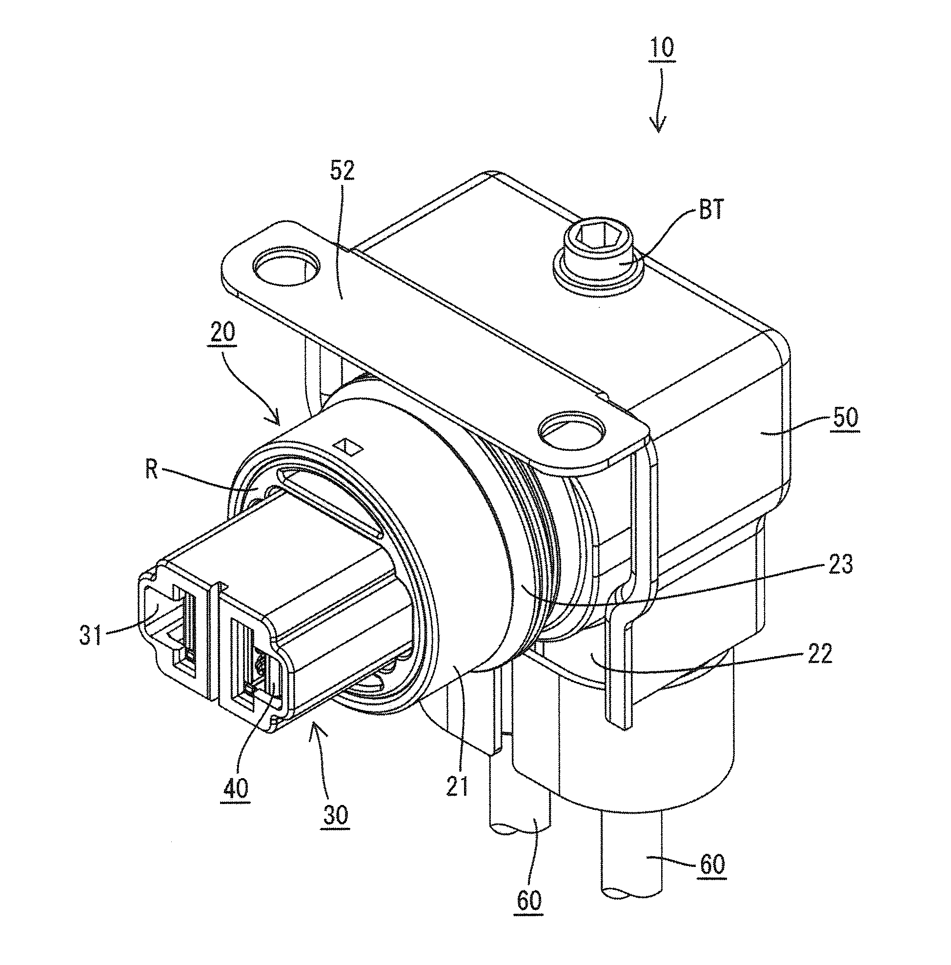
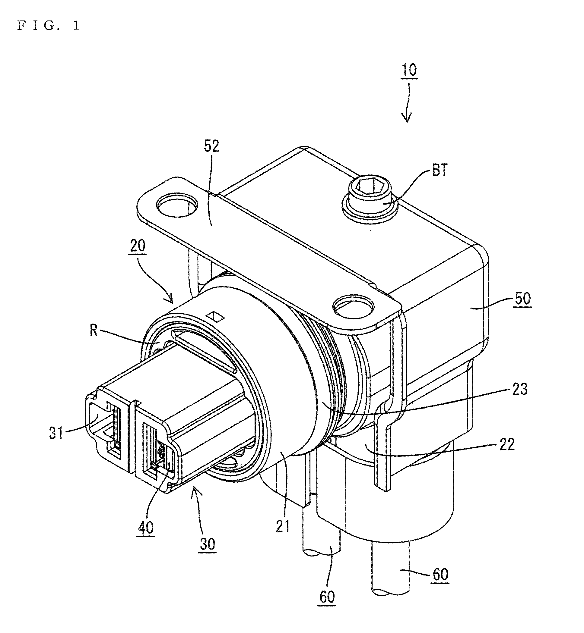
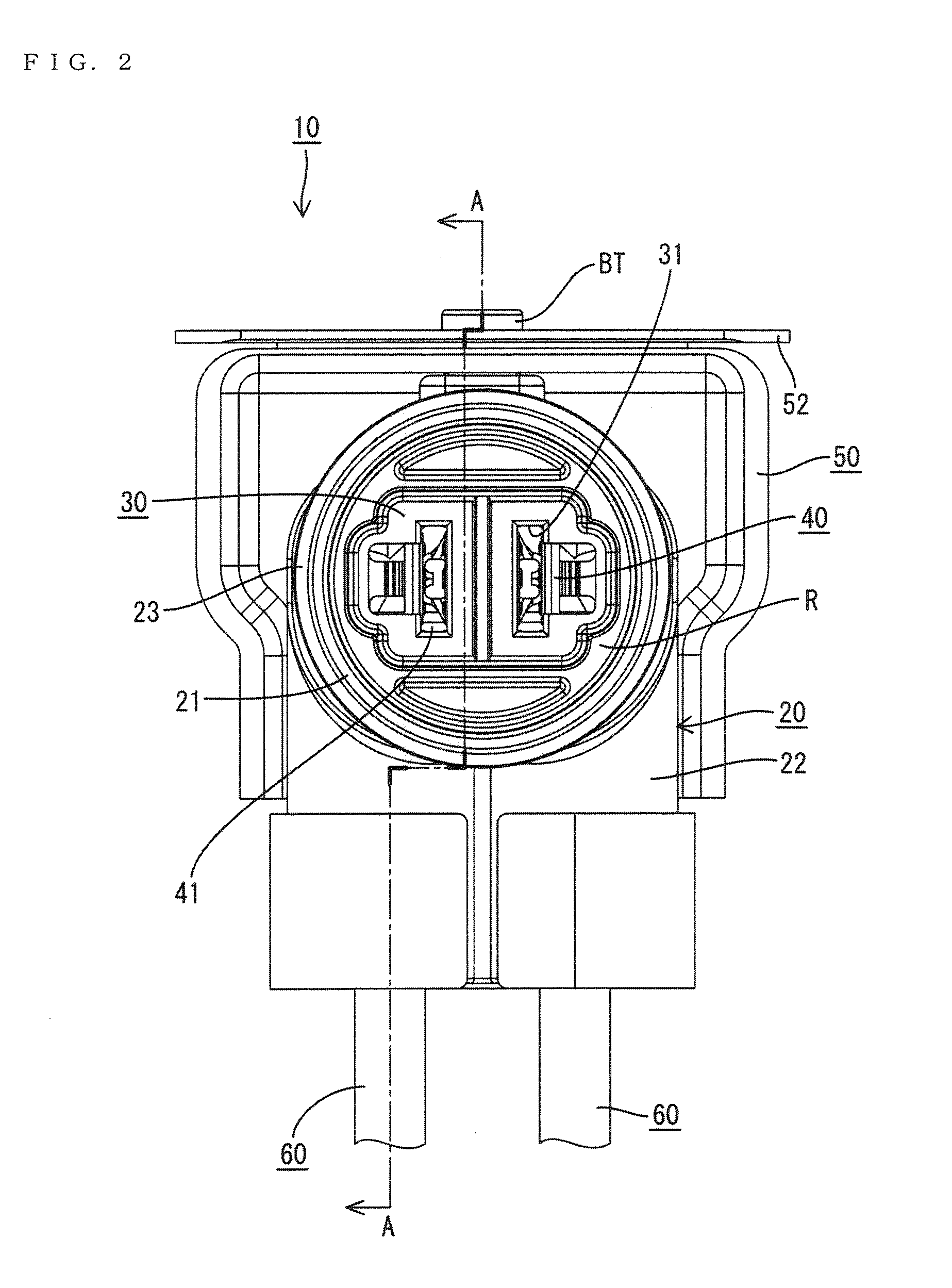
[0030]A connector in accordance with the invention is identified by the numeral 10 in FIGS. 1-12. The connector 10 accommodates high-voltage wires 60 and is mounted on a shield case (not shown) of a device (e.g. inverter, motor or the like of a vehicle such as a hybrid vehicle or an electric vehicle). A device-side connector (not shown) is connectable to the connector 10 is arranged at a position facing the connector 10 in a connecting direction in the shield case. In the following description, a vertical direction is based on that of FIG. 3 and a lateral direction is based on that of FIG. 2. Further, forward and backward directions are based on lateral directions of FIG. 3, with a left direction (connecting direction to the device-side connector) referred to as a forward direction and a right direction referred to as a backward direction.

[0031]As shown in FIG. 4, the connector 10 includes a substantially L-shaped housing main body 20, a front housing 30 connectable to the device-si...


PUM


Abstract

A connector (10) into which wires (60) each formed by covering a flexible core (61) with an insulation coating (62) are introduced includes female terminals (40) to be connected to ends of the wires (60), and a housing main body (20) for accommodating end portions of the wires (60) connected to the female terminals (40). Vibration absorbing portions (63) formed by removing the insulation coatings (62) are provided in parts of the wires (60) to be accommodated into the housing main body (20).

Description

BACKGROUND[0001]1. Field of the Invention[0002]The present invention relates to a connector.[0003]2. Description of the Related Art[0004]Japanese Unexamined Patent Publication No. 2000-277217 discloses a connector that prevents trouble in connector connection due to a dimensional accuracy error. This connector has a spring washer with a leaf spring arranged between a connector main body and a bottom plate. The leaf spring deflects when a mating connector is inserted, and the connector main body pivots according to the position of the mating connector.[0005]The above-described connector may be mounted on an end of a wire fixed to a vehicle, and a wire pulled out from the connector main body vibrates with vibration of the vehicle. This vibration is transmitted to a terminal connected to an end of the wire via the wire arranged in the connector main body and may cause trouble in connected parts of the terminal and a mating terminal provided in the mating connector.[0006]An intermediate...

Claims


Application Information

Patent Timeline
IPC IPC(8): H01R13/533
CPCH01R13/533H01R13/5825H01R24/38
Inventor ITSUKI, KIYOTAKAMIYAZAKI, SHO
Owner SUMITOMO WIRING SYST LTD
Why Eureka
Try Eureka