
Shock-absorbing member

Inactive Publication Date: 2014-05-08
TOYOTA SHATAI KK
View PDF8 Cites 8 Cited by
  • Summary
  • Abstract
  • Description
  • Claims
  • Application Information

AI Technical Summary

Benefits of technology

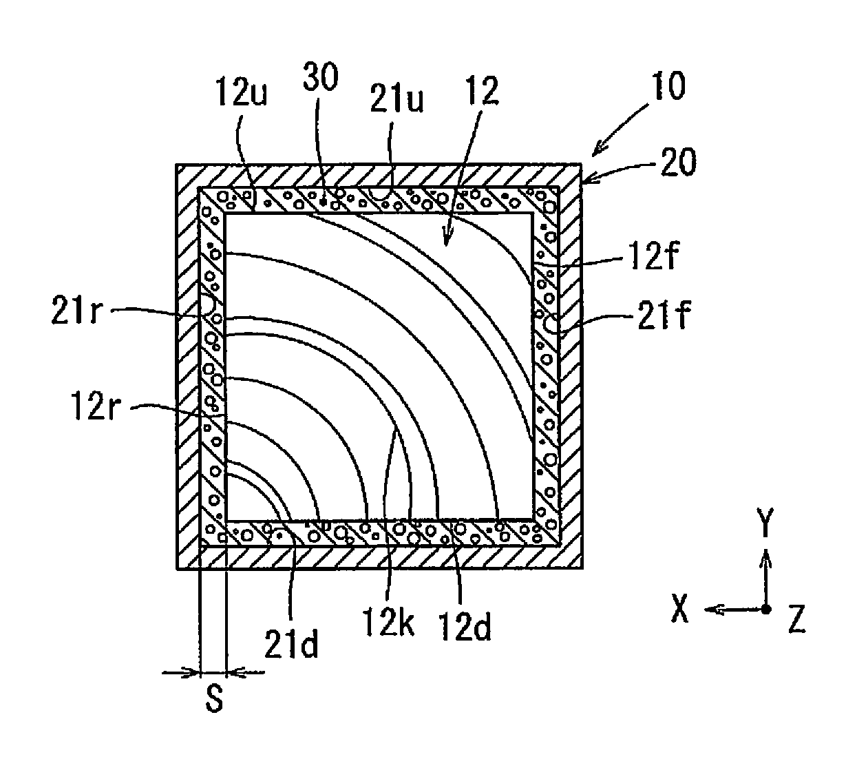
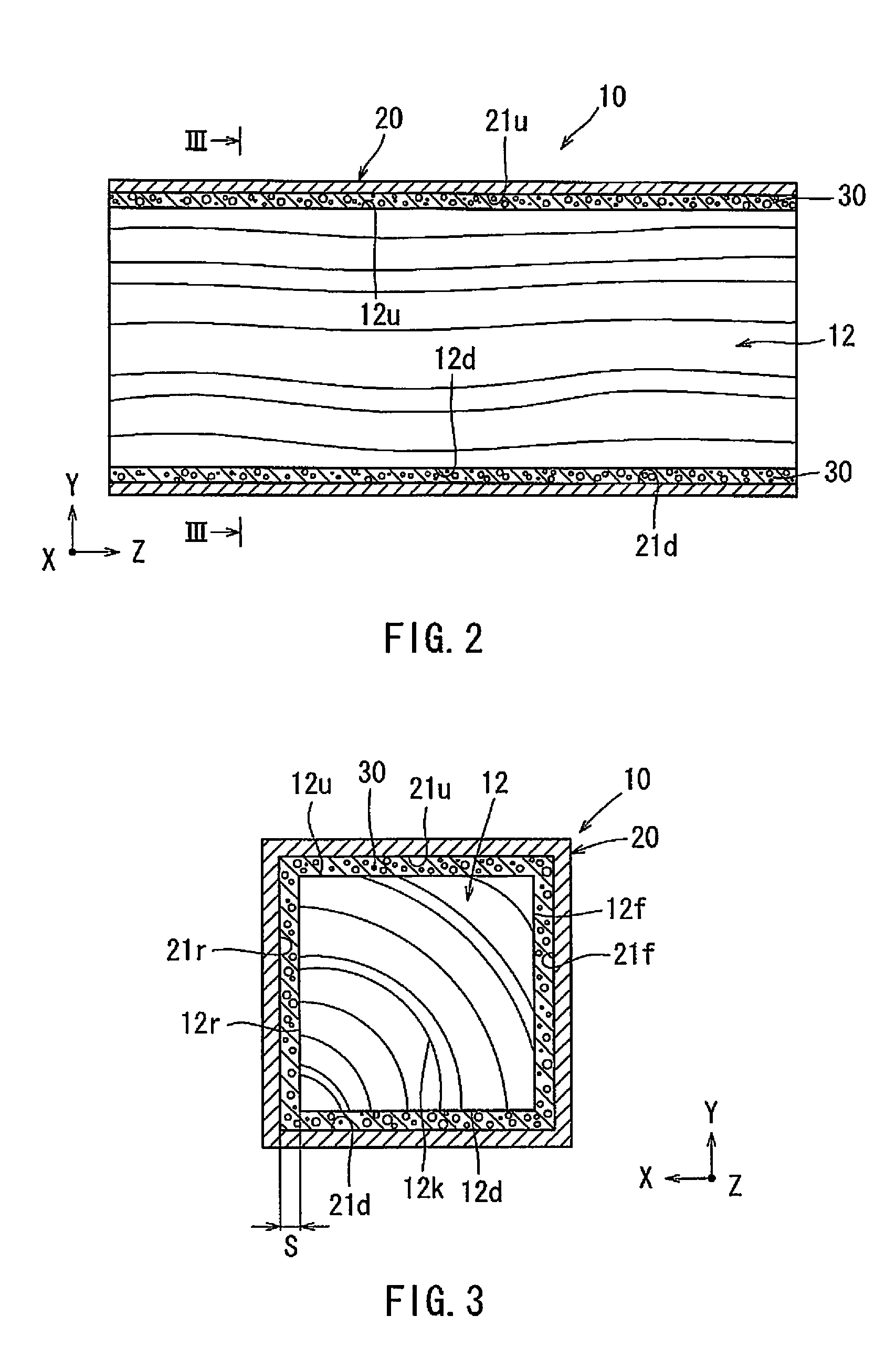
The present invention provides a shock-absorbing member that includes a cylindrical member, a wood member, and a foam material. The foam material is filled in the clearance between the wood member and the cylindrical member, securing the wood member without contacting it. The foam material does not prevent the cylindrical member from being deformed radially inwardly when compressed. This allows the wood member to be compressed into the bellows-shape, providing effective support to prevent collapse under a large load. The structure of the shock-absorbing member is simplified, reducing costs.

Problems solved by technology

The foamed foam material has a strength that does not prevent the cylindrical member from radially inwardly deforming when the cylindrical member is axially compressed with the wood member by the impact load.
Further, when the cylindrical member is axially compressed with the wood member due to the impact load, the foam material may not prevent the cylindrical member from being deformed radially inwardly.

Method used


Image

  • Shock-absorbing member
  • Shock-absorbing member
  • Shock-absorbing member

Examples


embodiment 1

[0035]In the following, a shock-absorbing member according to Embodiment 1 of the present invention will be described with reference to FIG. 1 to FIG. 8.

[0036]Further, an X-direction (a horizontal direction), a Y-direction (a vertical direction) and a Z-direction (a longitudinal direction) in the drawings respectively correspond to a width direction, a height direction and a front-back direction of a vehicle to which the shock-absorbing member is attached.

10>

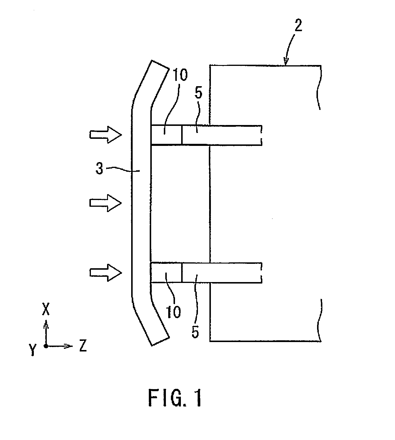
[0037]A shock-absorbing member 10 according to the present embodiment may be a member that is capable of receiving an impact load generated in the event of a vehicle collision and absorbing the impact load. As shown in FIG. 1, the shock-absorbing member 10 may be attached to each of crushable boxes that are disposed between a bumper reinforcement member 3 of a front bumper (not shown) and right and left side members 5 of a vehicle 2.

21 Regarding the Structure of the Shock-Absorbing Member 10>

[0038]As shown in FIG. 2 and FIG. 3, ...


PUM


Abstract

A shock-absorbing member may include a cylindrical member configured to receive an impact load applied axially and capable of being axially compressed by the impact load, a wood member received within the cylindrical member without contacting each other and having an impact load-resistance strength greater than the cylindrical member, and a foam material capable of positioning the wood member with respect to the cylindrical member and filled in a clearance formed between an outer surface of the wood member and an inner wall surface of the cylindrical member partially or over the entirety thereof by foaming. The foamed foam material has a strength that does not prevent the cylindrical member from radially inwardly deforming when the cylindrical member is axially compressed with the wood member by the impact load.

Description

PRIORITY CLAIM[0001]The present application is a National Phase entry of PCT Application No. PCT / JP2011 / 076152, filed Nov. 14, 2011, which claims priority to Japanese Patent Application No. 2011-090154, filed Apr. 14, 2011, the disclosure of which are hereby incorporated by reference herein in their entirety.TECHNICAL FIELD[0002]The present invention relates to a shock-absorbing member that is configured to be capable of receiving an impact load generated in the event of a vehicle collision or other such accidents and effectively absorbing the impact load.BACKGROUND ART[0003]Japanese Laid-Open Patent Publication No. 2001-246995 discloses art relating to a shock-absorbing member that is configured to be capable of receiving an impact load generated in the event of a vehicle collision or other such accidents and absorbing the impact load.[0004]As shown in FIG. 9, a shock-absorbing member 100 described in Japanese Laid-Open Patent Publication No. 2001-246995 is composed of an aluminum ...

Claims


Application Information

Patent Timeline
IPC IPC(8): F16F7/12B60R19/34
CPCB60R19/34F16F7/121B60R19/03
Inventor OKUDA, NOBUHISA
Owner TOYOTA SHATAI KK
Learn More