Modular hybrid electric vehicle rotor hub

a hybrid electric vehicle and rotor hub technology, applied in the direction of fluid couplings, gearings, couplings, etc., can solve the problem of requiring an expensive rotor hub

Active Publication Date: 2014-05-08
FORD GLOBAL TECH LLC
View PDF6 Cites 18 Cited by
  • Summary
  • Abstract
  • Description
  • Claims
  • Application Information

AI Technical Summary

Problems solved by technology

Nesting the disconnect clutch inside the motor rotor allows improves packaging but generally requires an expensive rotor hub since it must hold the rotor, clutch piston and clutch plates.

Method used


Image

  • Modular hybrid electric vehicle rotor hub
  • Modular hybrid electric vehicle rotor hub
  • Modular hybrid electric vehicle rotor hub

Examples


Embodiment Construction

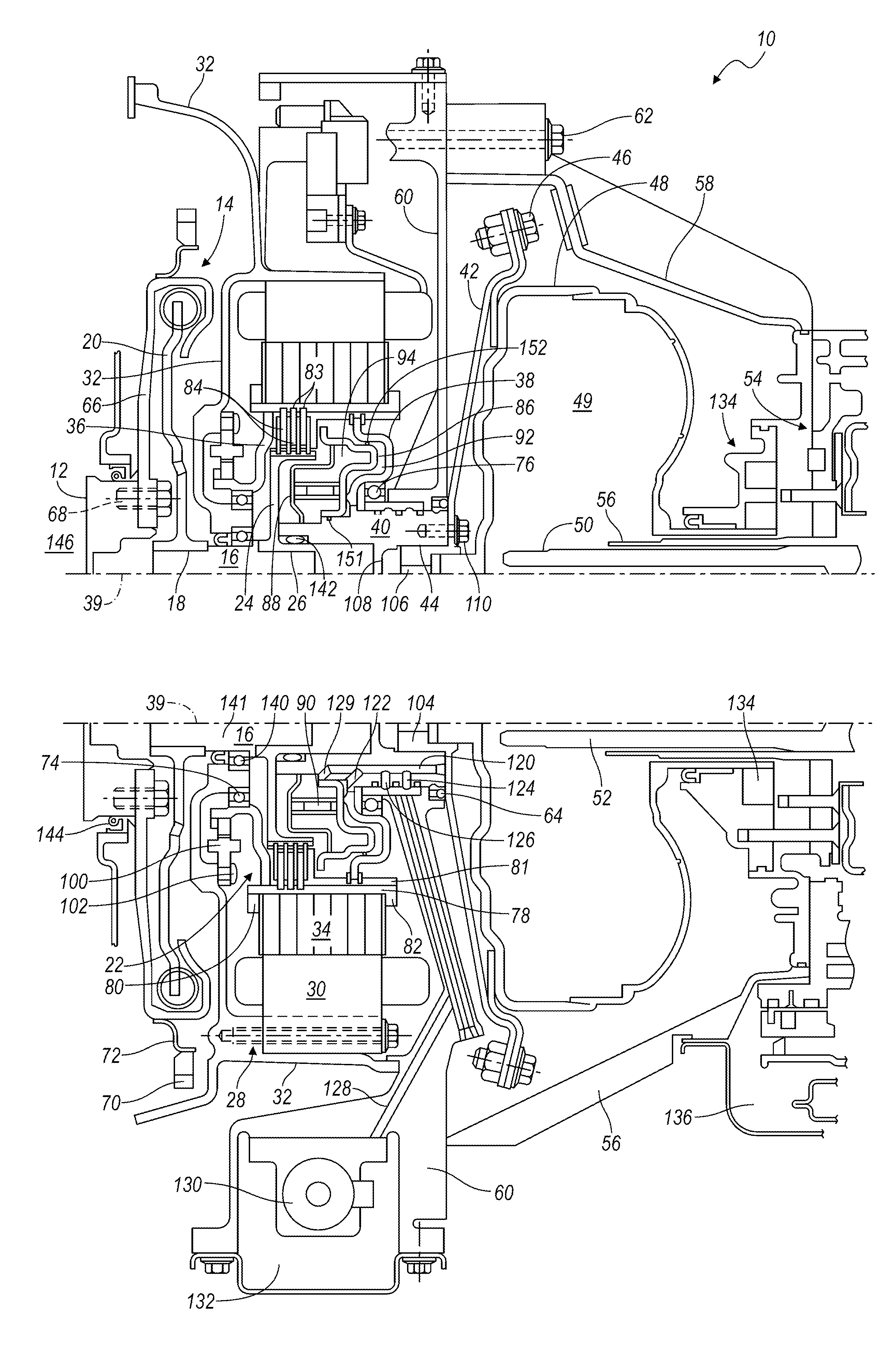
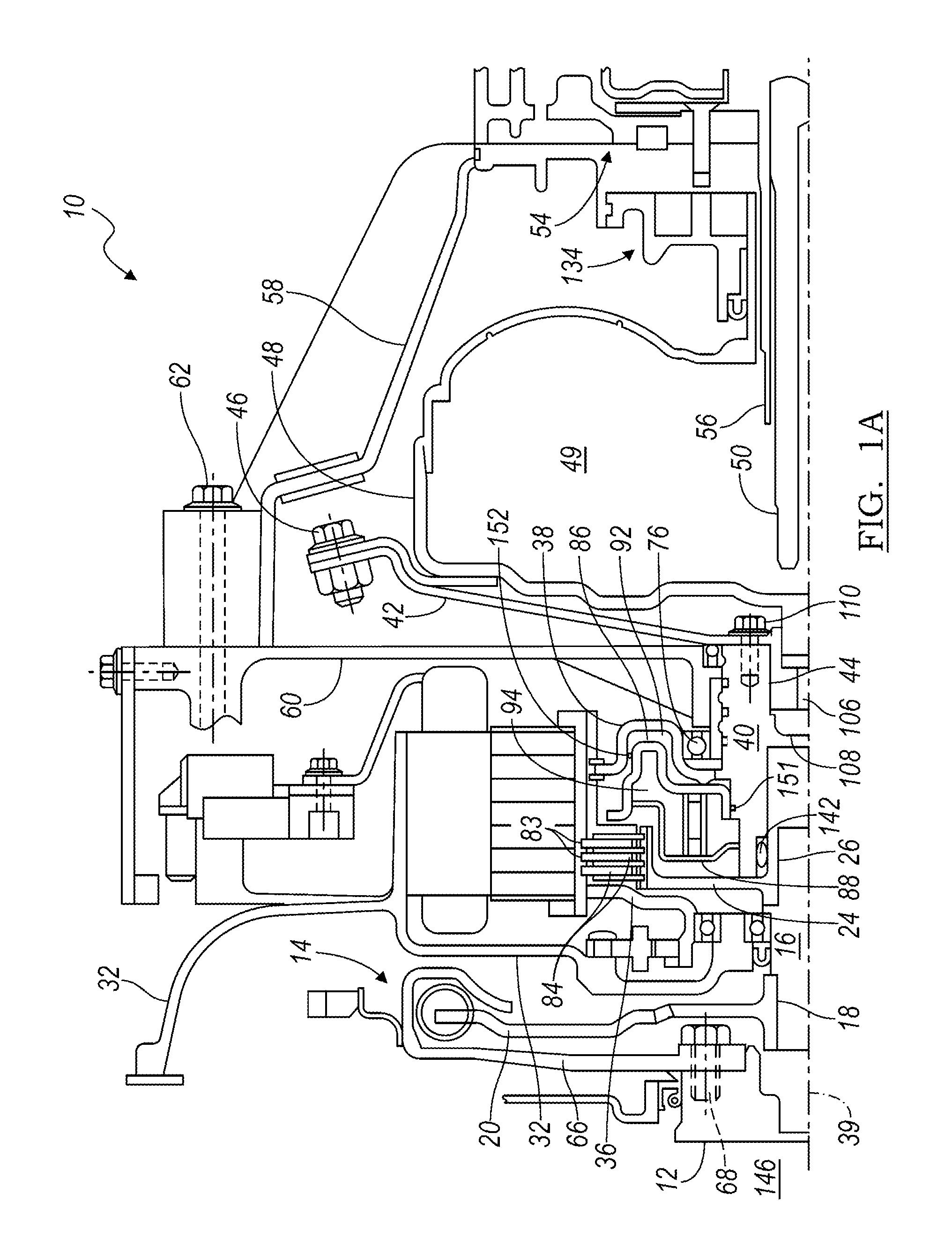
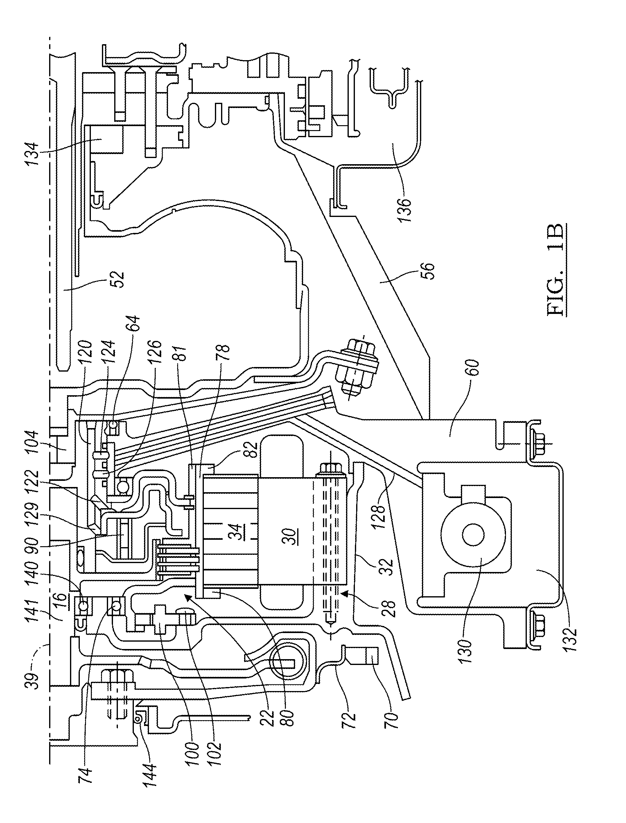
[0019]FIGS. 1A and 1B illustrate a module 10 of a powertrain for a hybrid electric vehicle that includes an engine having a rotary output 12; a torsional damper 14, secured to the engine output 12; an input shaft 16, secured by a spline 18 to an output 20 of damper 14; a disconnect clutch 22, supported on a clutch hub 24 that is secured by a spline 26 to input shaft 16; an electric machine 28, which includes a stator 30 bolted to a front bulkhead 32 and a rotor 34 supported by a first leg 36 and a second leg 38 for rotation about an axis 39; a rotor hub 40, secured preferably by a weld to leg 38; and a flexplate 42, secured at one end by a spline connection 44 to rotor hub 40 and secured at the opposite end by bolts 46 to a torque converter casing 48, which encloses a hydrokinetic torque converter 49. The electric machine 28 may be an electric motor or an electric motor-generator.

[0020]Torque converters suitable for use in the powertrain are disclosed in and described with reference...


PUM

PropertyMeasurementUnit
axis of rotationaaaaaaaaaa
transmissionaaaaaaaaaa
Centrifugal forceaaaaaaaaaa

Abstract

A rotor hub includes a sheet metal cylinder including spline teeth including angularly spaced crests and valleys, a tube surrounding the cylinder, secured to the crests and supporting a rotor thereon, a hub secured to the cylinder and supported for rotation, a torque converter, and a flex plate secured to the hub and the torque converter.

Description

CROSS REFERENCE TO RELATED APPLICATIONS[0001]This is a continuation-in-part application of pending U. S. application Ser. No. 13 / 362,018, filed Jan. 31, 2012.BACKGROUND OF INVENTION[0002]This invention relates to a powertrain of hybrid electric vehicles, particularly to a powertrain module that can be installed between and secured to an engine output and a transmission input.[0003]Hybrid electric vehicles (HEVs) have both an internal combustion engine and an electric machine, which are alternately, or in combination, used to propel the vehicle. A variety of different powertrains are used in hybrid vehicles such as a parallel configuration, in which the engine is connected to the motor by a disconnect clutch with the motor driving a torque converter input of an automatic power transmission. The transmission has an output which is connected to a differential coupled to the two driven wheels of the vehicle.[0004]A need exists in the industry for a hybrid electric powertrain that includ...

Claims


Application Information

Patent Timeline
Patent Type & Authority Applications(United States)
IPC IPC(8): F16D33/18
CPCF16D33/18B60K6/405B60K6/48B60Y2304/076B60Y2400/426Y10T29/49826Y10S903/914Y02T10/62B21J5/00B21K1/762B60K6/387F16D25/06F16H45/02F16H2045/0215F16H2045/0221
Inventor FRAIT, STEVEN A.BREVICK, JOHN E.DEVEREAUX, KEITH A.
Owner FORD GLOBAL TECH LLC
Why Eureka
Try Eureka