Method of annealing metal member

a metal member and metal technology, applied in the field of metal member annealing, can solve the problems of poor productivity of laminated core annealing, lack of specific heating method in patent document 3, and difficulty in uniformly bringing electrodes into contact with laminated core, so as to reduce the time required for heating, improve productivity, and maintain the effect of removing the strain occurring in the teeth

Active Publication Date: 2014-05-08
NIPPON STEEL CORP
View PDF13 Cites 2 Cited by
  • Summary
  • Abstract
  • Description
  • Claims
  • Application Information

AI Technical Summary

Benefits of technology

[0009]According to the present invention, it is possible to heat the metal member from the inner space by infrared light radiated from a first heater disposed so as to extend parallel to the central axis direction of the metal member. Further, it is possible to bring the first heater close to the teeth at equal distances throughout the entire length of the central axis direction of each of the teeth formed on the inner peripheral surface of the metal member. This makes it possible to reduce the time required for heating, compared to the configuration of heating the metal member by a heating furnace. Thus, it is possible to improve productivity concerning annealing the metal member. Further, the teeth formed on the inner peripheral surface of the metal member can be heated, which makes it possible to maintain and enhance the effect of removing the strain occurring in the teeth, and further reducing the iron loss. As described above, according to the present invention, it is possible to improve the productivity by reducing the heating time, and at the same time, to prevent deterioration in the effect of reducing iron loss during annealing.

Problems solved by technology

This leads to a problem of poor productivity of annealing of the laminated core.
However, Patent Document 3 does not disclose any specific heating method.
However, with the method of heating through electric power, it is difficult to uniformly bring the electrodes into contact with the laminated core if the size of the laminated core is large.
Thus, it is difficult to uniformly heat the laminated core in a short period of time.

Method used


Image

  • Method of annealing metal member
  • Method of annealing metal member
  • Method of annealing metal member

Examples


first embodiment

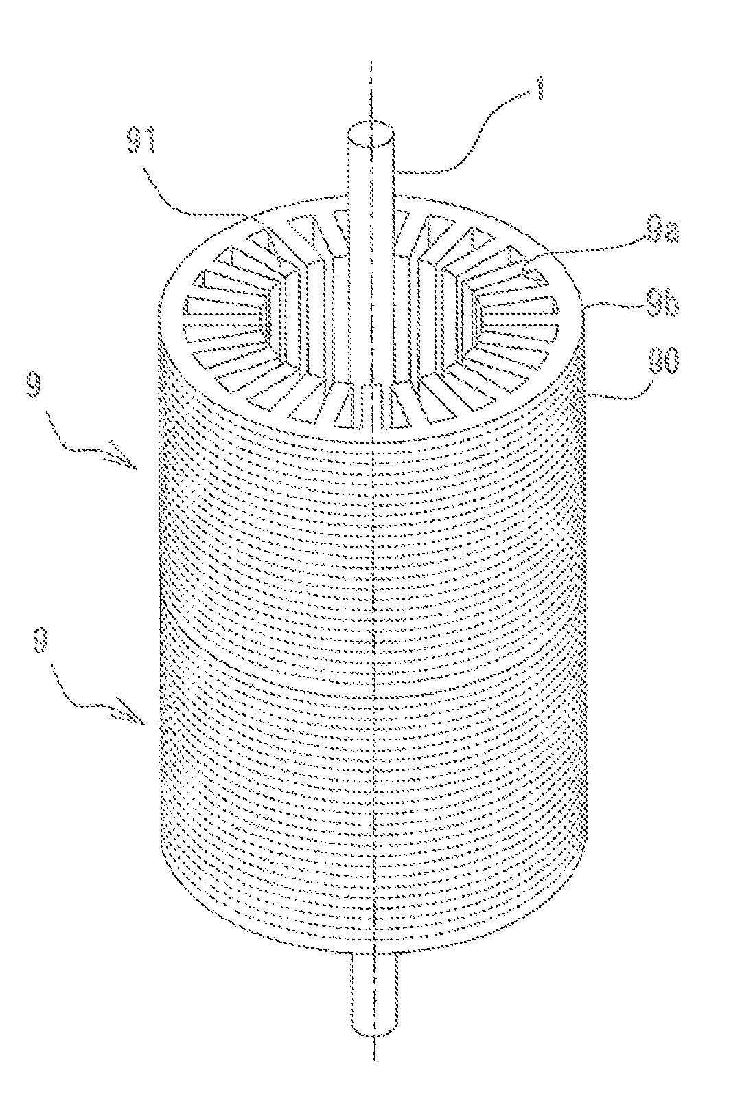
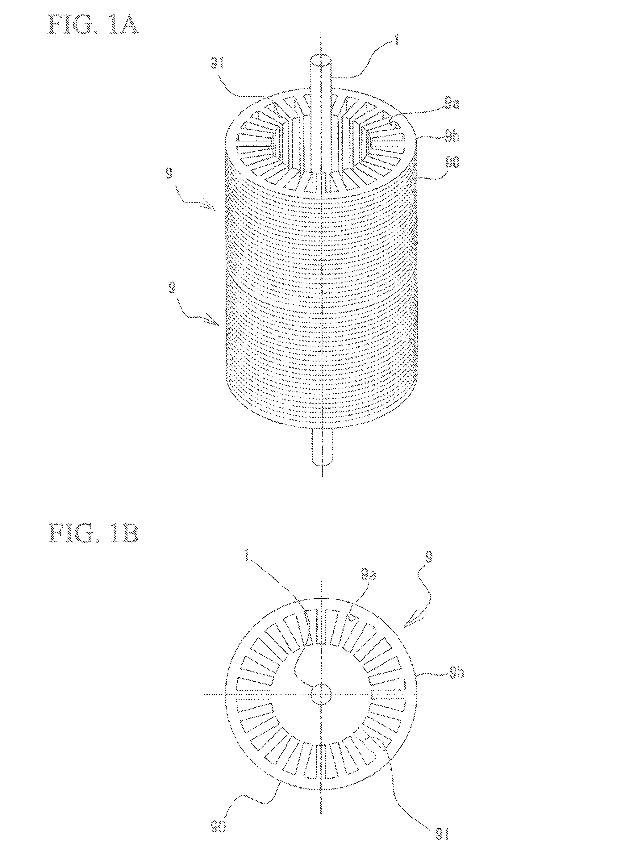
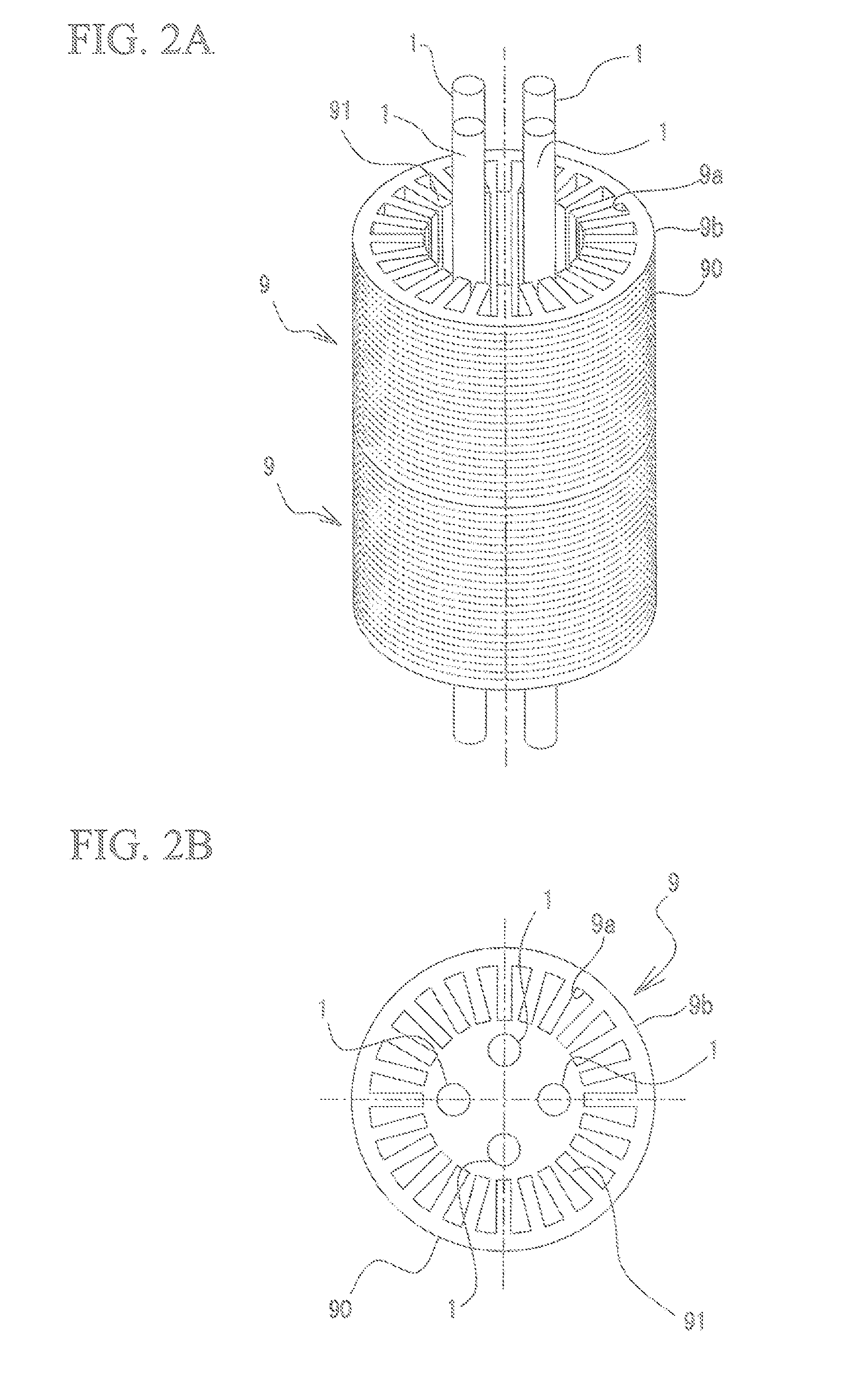
[0027]FIG. 1A and FIG. 2A are perspective views each schematically illustrating a method of annealing a laminated core according to a first embodiment. FIG. 1B and FIG. 2B are plan views each schematically illustrating a method of annealing a laminated core according to the first embodiment.

[0028]The method of annealing a laminated core according to the first embodiment is capable of annealing a laminated core 9 having a conventional general configuration. The configuration of the laminated core 9 will be briefly described below. The laminated core 9 is formed by laminating electromagnetic steel sheets 90 that have been punched into a predetermined shape, and has a hollow cylindrical shape as a whole. The laminated core 9 has an inner peripheral surface 9a having teeth 91 formed thereon. The teeth 91 are each configured so as to protrude toward the center in the radial direction, and are arranged in the circumferential direction so as to be spaced away from each other at a predeterm...

second embodiment

[0043]Next, a second embodiment according to the present invention will be described. Note that the configuration common to that of the first embodiment will not be described. FIG. 4A is a perspective view schematically illustrating a method of annealing a laminated core according to the second embodiment. FIG. 4B is a plan view schematically illustrating a method of annealing a laminated core according to the second embodiment.

[0044]As illustrated in FIG. 4A and FIG. 4B, the first heaters 1 are inserted in the inner space of the laminated core 9, and are disposed so as to be brought close to the teeth 91. Further, a first separator 2a is provided between the first heaters 1. The first separator 2a has a function of blocking the infrared light coming from the adjacent first heaters 1 in a manner such that the first heaters 1 do not directly radiate the infrared light onto each other. Further, the first separator 2a also has a function of reflecting the infrared light radiated from e...

third embodiment

[0049]Next, a third embodiment according to the present invention will be described. Note that the configuration common to that of the first embodiment will not be described. FIG. 5A is a perspective view schematically illustrating a method of annealing a laminated core according to the third embodiment. FIG. 5B is a plan view schematically illustrating a method of annealing a laminated core according to the third embodiment.

[0050]As illustrated in FIG. 5A and FIG. 5B, in the third embodiment, the first heaters 1 are inserted in the inner space of the laminated core 9, and are disposed between the teeth 91 formed on the inner peripheral surface 9a of the laminated core 9. Further, the laminated core 9 is heated from the inner space by the first heaters 1 disposed between the teeth 91.

[0051]According to the third embodiment, it is possible to bring the first heaters 1 close to the surface of the teeth 91 formed on the inner peripheral surface 9a of the laminated core 9. In particular...


PUM

PropertyMeasurementUnit
wavelength bandwidthaaaaaaaaaa
temperatureaaaaaaaaaa

Abstract

Provided is a method of annealing a metal member, including: disposing a first heater in an inner space of a hollow cylindrical metal member having an inner peripheral surface provided with plural teeth protruding toward a central direction, the first heater radiating infrared light and being disposed so as to extend parallel to a direction of a central axis of the metal member; heating the metal member from the inner space with the first heater; and gradually cooling the metal member after heating.

Description

TECHNICAL FIELD[0001]The present invention relates to a method of annealing a metal member having a hollow cylindrical shape. More specifically, the present invention relates to a method of annealing a metal member favorable for annealing a laminated core formed by laminating, for example, electromagnetic steel sheets, and the annealing method is directed to removing strain to reduce iron losses. The present application claims priority based on Japanese Patent Application No. 2012-013403 filed in Japan on Jan. 25, 2012, the disclosures of which are incorporated herein by reference in their entirety.BACKGROUND ART[0002]General laminated cores for use in electric motors are formed by punching an electromagnetic steel sheet into a predetermined shape, laminating the punched sheets, and joining the sheets, for example, through welding or caulking. However, during the punching, strain may occur in the electromagnetic steel sheet. Once the strain occurs in the electromagnetic steel sheet,...

Claims


Application Information

Patent Timeline
Patent Type & Authority Applications(United States)
IPC IPC(8): C21D9/00
CPCC21D9/0068C21D1/09C21D1/26C21D1/34C21D8/12C21D9/00F27B5/14F27B2005/143F27D11/02H02K15/024H02K15/12
Inventor OHSUGI, YASUOHAMAYA, TSUYOSHIARAI, SATOSHIYANAGIDA, EIJISANO, SHINYAKONDA, MASAAKITAKAHASHI, TOSHIMITSUSATO, YOJI
Owner NIPPON STEEL CORP
Why Eureka
Try Eureka