Passive Standing Apparatus

a standing apparatus and passive technology, applied in the field of passive standing apparatus, can solve the problems of difficult disassembly and assembly of many other standing devices, unusable device movement, and inability to easily transport, etc., and achieve the effect of promoting muscle stretching, easy positioning and attaching

Inactive Publication Date: 2014-05-08
WILLIAMSON III ZACK ANDREW +1
View PDF3 Cites 2 Cited by
  • Summary
  • Abstract
  • Description
  • Claims
  • Application Information

AI Technical Summary

Benefits of technology

[0020]Standing also reduces both the incidence and severity of lower limb spasticity (Odeen & Knuttson, 1981).
[0025]Another primary benefit gained from standing by persons with some form of lower limb paralysis is improvement to functional status and morale. The ability to perform tasks while concurrently standing has been shown to have significant, positive psychological effects on those bedridden or wheel chair bound.
[0027]In one embodiment of the invention, a wedge is provided for the user to stand upon, the use of which is intended to elevate the user's toes above his heels, placing the user's feet in the dorsiflexed position. The dorsiflexed foot position promotes muscle stretching, a physiological benefit to users.
[0028]In another embodiment of the invention, a rigid table is provided to be easily positionable and attachable to the handrails of the frame so that the user may position objects upon the table for use in performing tasks.

Problems solved by technology

Many of the other standing devices available are mounted on casters, creating the possibility of undesirable movement of the device.
Many of the other standing devices available are complicated to partially disassemble and are not easily transportable.

Method used


Image

  • Passive Standing Apparatus
  • Passive Standing Apparatus
  • Passive Standing Apparatus

Examples


Embodiment Construction

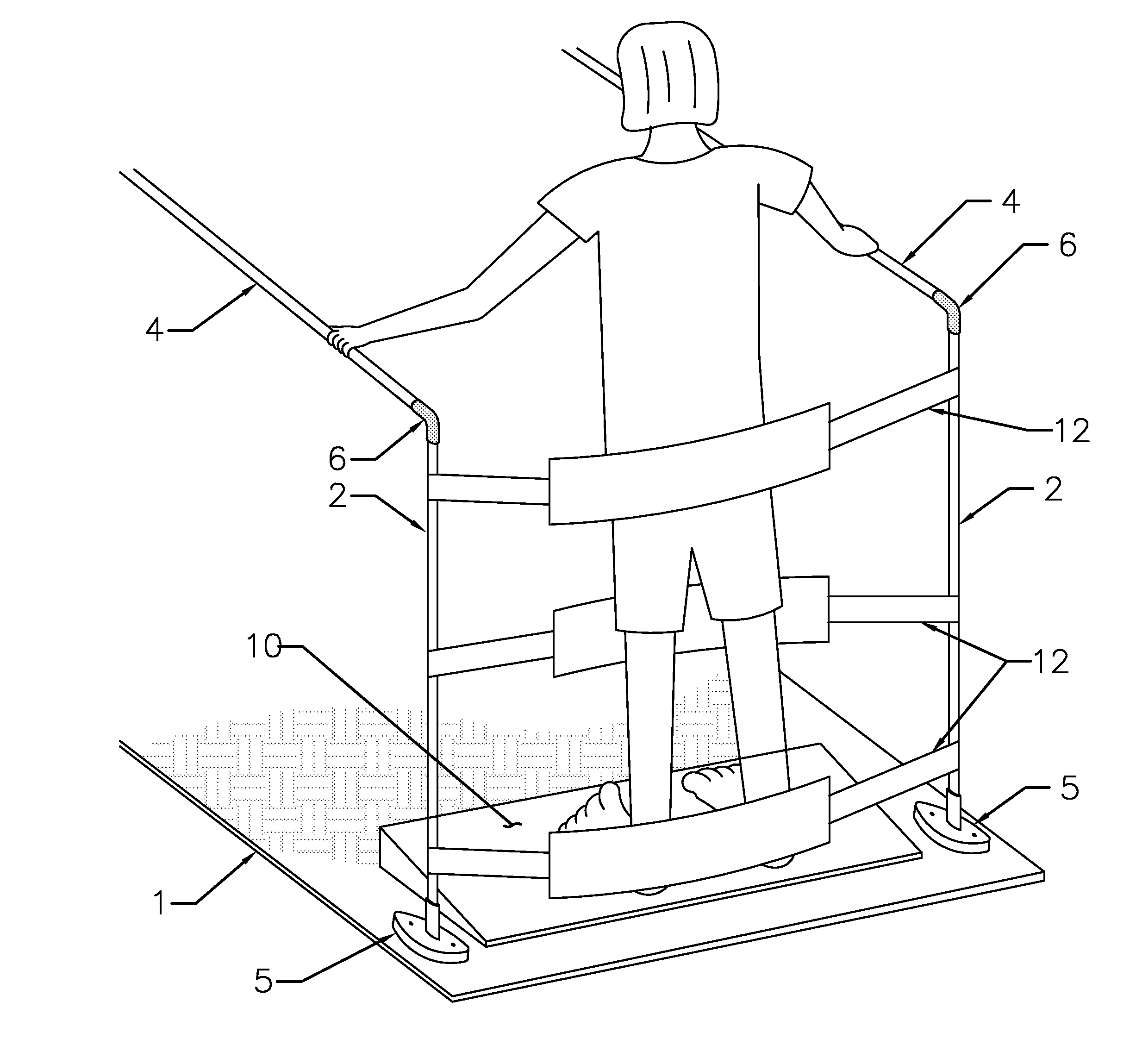
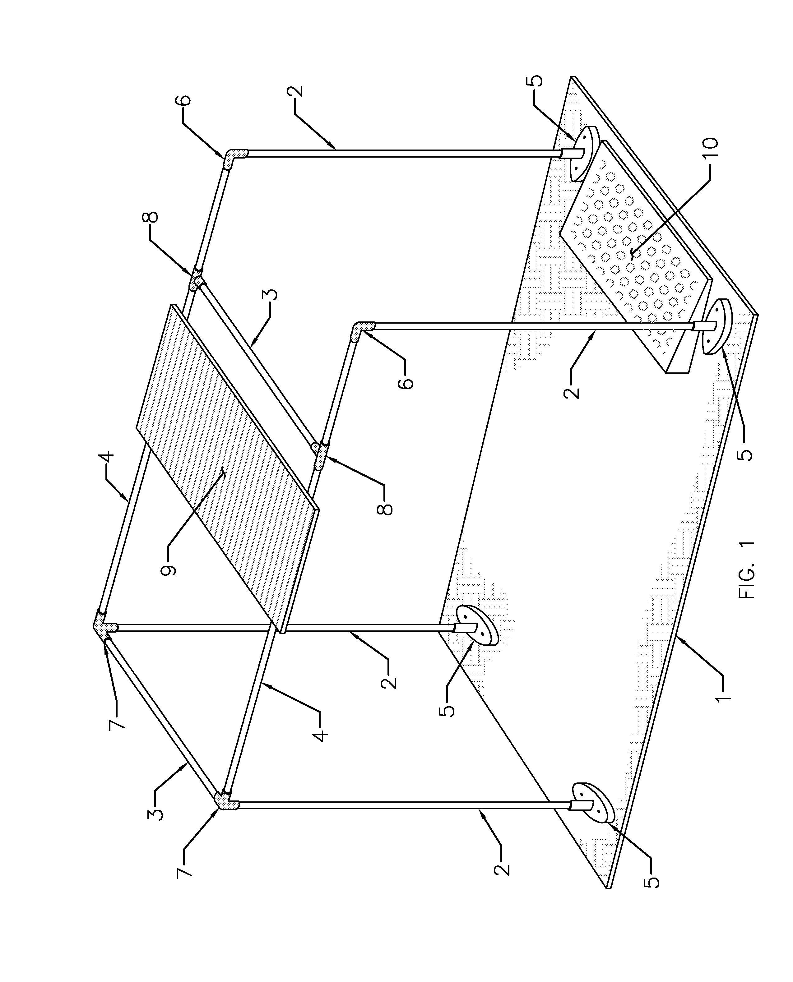
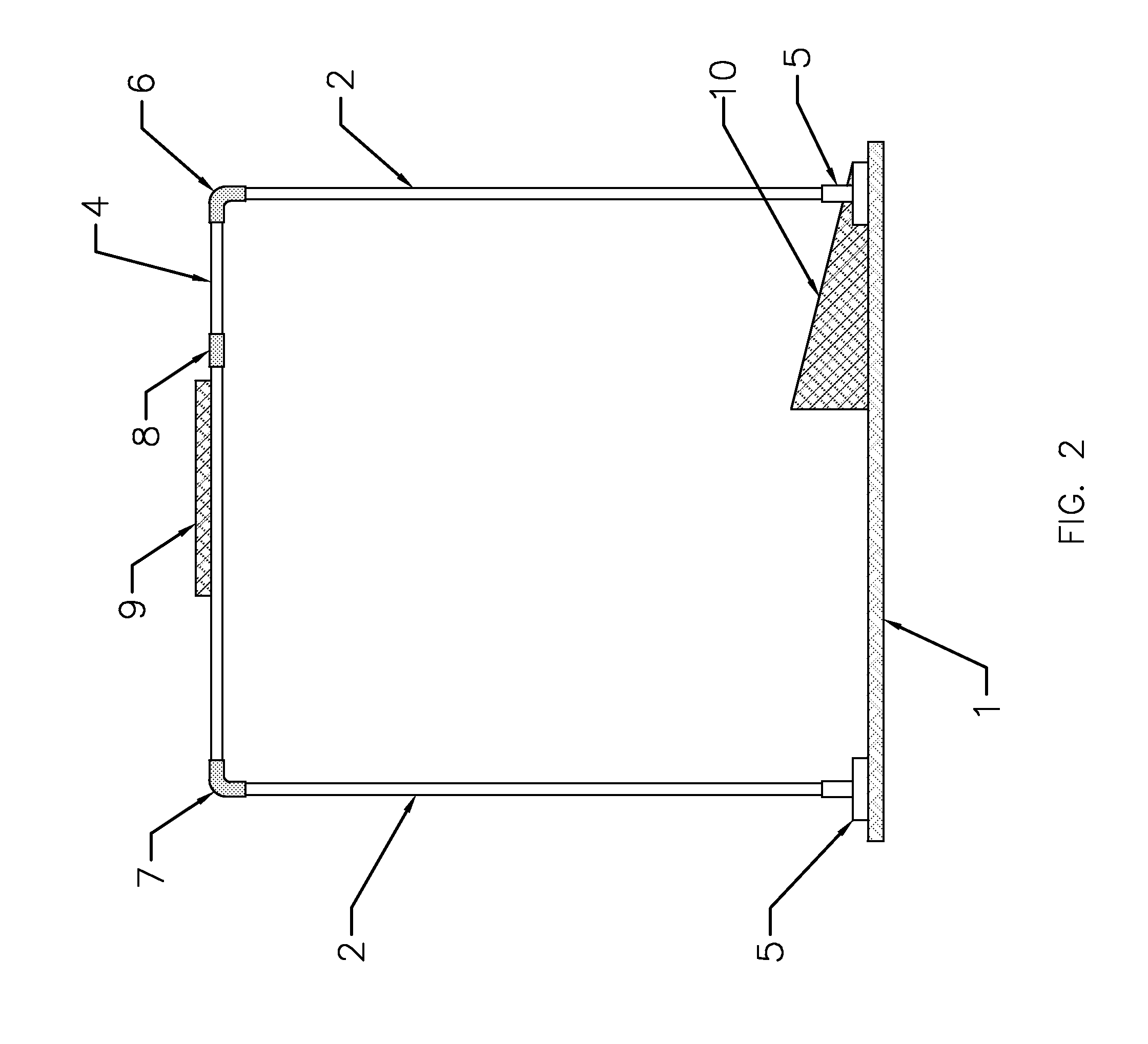
[0038]Referring now to the drawings, particularly FIGS. 1-3, a passive standing apparatus includes a rigid tubular top frame attached to a rectangular base 1 by a plurality of vertical rigid tubular legs 2. The top frame attachments to the vertical legs and the vertical legs attachments to the base are provided using rigid slip-on fittings 5, 6, 7, and 8. FIGS. 7-10 further depict these rigid fittings 5, 6, 7, and 8 used as components of the invention. The rigid fittings 5, 6, 7, and 8 are constructed such that the tubular elements of the top frame 3 and 4 and vertical legs 2 fit closely into each rigid fitting and are secured within the fitting by means of one or more hardened, recessed set screws.

[0039]The top frame comprises two parallel, horizontal handrails 4, a plurality of horizontal cross members 3 arranged perpendicularly to 4, and rigid fittings 6, 7, and 8. Handrails 4 are rigidly attached at each extremity to a rigid fitting 6 and 7. Rigid fittings 6 are utilized at the ...


PUM


Abstract

This is an apparatus used to support a paretic or paraplegic user in a standing position. The apparatus includes a top tubular frame supported by a plurality of vertical tubular members attached to a base. The top frame is open at the front such that a user may position a wheelchair at the opening, in close proximity to the apparatus, and transfer from the wheelchair to the apparatus. The apparatus further includes flexible straps attachable to the two vertical tubular members nearest the opening of the frame. The flexible straps, after having been positioned in strategic locations along the user's lower limbs, function to maintain the user in a standing position. The apparatus further includes a positionable attachable table that augments a user's ability to perform other tasks while standing. The apparatus further includes a wedge upon which the user may stand to maintain dorsiflexed feet position.

Description

CROSS-REFERENCE TO RELATED APPLICATIONS[0001]This application claims the benefit of U.S. Provisional Application No. 61 / 643,247, filed May 5, 2012.STATEMENT REGARDING FEDERALLY SPONSORED RESEARCH OR DEVELOPMENT[0002]Not ApplicableREFERENCE TO SEQUENCE LISTING, A TABLE, OR A COMPUTER PROGRAM LISTING COMPACT DISC APPENDIX[0003]Not ApplicableBACKGROUND OF THE INVENTION[0004]1. Field of the Invention[0005]This invention relates generally to a stand used to support a paretic or paraplegic individual in an upright position to minimize or mitigate the deteriorative effects of prolonged sitting or recumbent positioning.[0006]2. Description of Prior Art[0007]There are numerous devices that can be used to assist a paretic or paraplegic individual attain a standing position. Some of these devices have methods to raise a wheel chair system into a standing position. Other devices have lifting mechanisms to move a user from a sitting position into a standing position. Other devices are used as a ...

Claims


Application Information

Patent Timeline
Patent Type & Authority Applications(United States)
IPC IPC(8): A61H1/00
CPCA61H1/0266A61G7/1038A61H2201/0161A61H2201/1284A61H2201/163A61H2201/1642A61H2203/0406
Inventor WILLIAMSON, III, ZACK ANDREWWILLIAMSON, GARETT LANG
Owner WILLIAMSON III ZACK ANDREW
Why Eureka
Try Eureka