Wheel loader

a technology of loader and loader body, which is applied in the field of loader, can solve the problems of unsatisfactory excavation workability and difficult lifting, and achieve the effects of accurate determination, improved maneuverability, and unnecessary control of work tools

Active Publication Date: 2014-05-08
KOMATSU LTD
View PDF14 Cites 13 Cited by
  • Summary
  • Abstract
  • Description
  • Claims
  • Application Information

AI Technical Summary

Benefits of technology

[0007]At this time, in a wheel loader that has been outfitted with a Z bar link mechanism, due to a structure whereby the bucket rotates upward to an appropriate degree simultaneously with upward rotation of the boom, the object will readily enter into the bucket through maneuvering of the boom only, without maneuvering the bucket. Furthermore, even in a case in which the operator continues upward maneuvering of the boom, the reaction force to which the work implement is subjected is moderated through upward rotation of the bucket to an appropriate degree. Stalling and / or a rise in hydraulic pressure of the boom cylinder is thereby kept to a minimum, and the boom is easily elevated, thereby providing good maneuverability when scooping.
[0025]In the wheel loader control method according to the eighth aspect of the present invention, the work tool is rotated upward automatically when the boom is rotated upward within an angular range below the horizontal direction during excavation. Satisfactory excavation workability can be obtained thereby, even when the operator does not perform maneuvering of the work tool simultaneously with maneuvering of the work boom.

Problems solved by technology

Therefore, with upward maneuvering of the boom only, the work implement is subjected to strong reaction force during excavation, making the boom hard to lift.
Therefore, when initiating excavation, unless the bucket is maneuvered to rotate upward simultaneously with upward maneuvering of the boom, satisfactory excavation workability is not obtained.
Satisfactory excavation workability can be obtained thereby, even when the operator does not perform maneuvering of the work tool simultaneously with maneuvering of the work boom.

Method used


Image

  • Wheel loader
  • Wheel loader
  • Wheel loader

Examples


Embodiment Construction

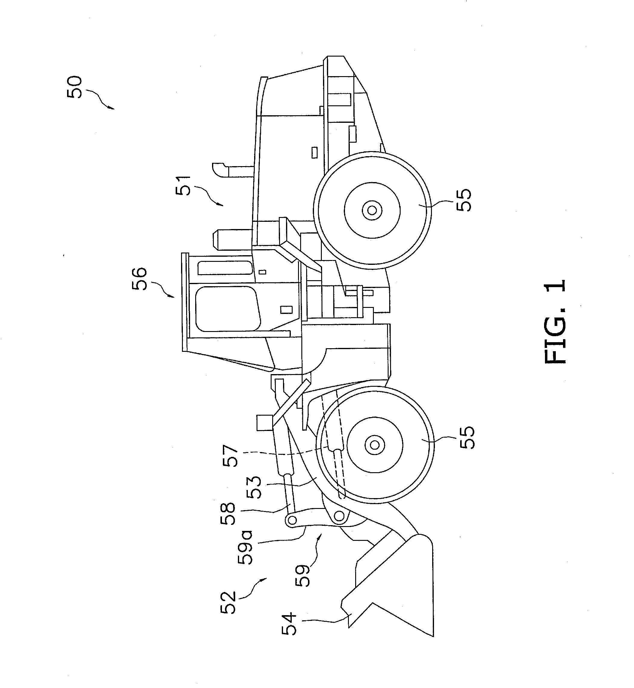
[0038]The following description of a wheel loader 50 according to an embodiment of the present invention employs the accompanying drawings. FIG. 1 is a perspective view of the wheel loader 50. The wheel loader 50 has a vehicle body 51, a work implement 52, a plurality of tires 55, a cab 56, and a link mechanism 59. The cab 56 is installed on the vehicle body 51. The work implement 52 is attached to the front section of the vehicle body 51. The work implement 52 has a boom 53, a bucket 54, a boom cylinder 57, and a bucket cylinder 58.

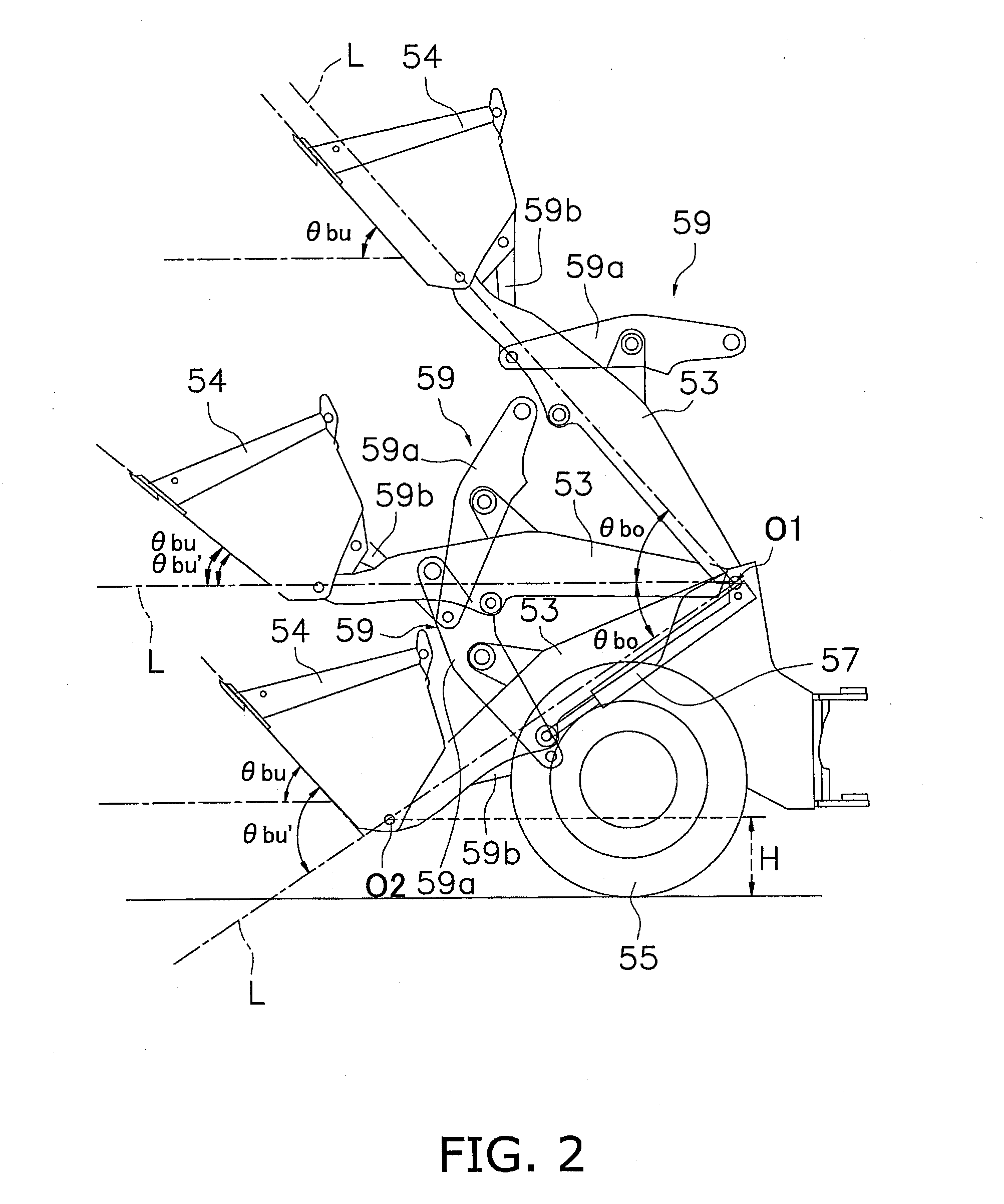
[0039]The boom 53 is a member for raising the bucket 54. The boom 53 is attached rotatably in the up and down directions to the vehicle body 51. The boom 53 is rotated up and down by the boom cylinder 57. The bucket 54 is attached rotatably in the up and down directions to the distal end of the boom 53. The bucket 54 is rotated up and down by the bucket cylinder 58. In the following description, “tilting” refers to an operation of rotating the bucket 54 ...


PUM


Abstract

A wheel loader includes a vehicle body, a work implement, a link mechanism and a control section. The work implement has a boom a work tool. The link mechanism is configured and arranged to change a relative angle of the work tool with respect to the boom when the boom is rotated upward, such that an amount of variation of an angle of the work tool with respect to a horizontal direction is less than an amount of variation of an angle of the work tool with respect to the horizontal direction when the boom is rotated upward while the work tool is at a fixed relative angle with respect to the boom. The control section is configured to execute an auto tilt control that causes the work tool to rotate upward when the boom is rotated upward within an angular range below the horizontal direction during excavation.

Description

CROSS-REFERENCE TO RELATED APPLICATIONS[0001]This application claims priority to Japanese Patent Application No. 2012-200521 filed on September 12, the disclosure of which is hereby incorporated herein by reference in its entirety.TECHNICAL FIELD[0002]The present invention relates to a wheel loader.BACKGROUND ART[0003]A wheel loader is provided with a vehicle body, and a work implement attached to the vehicle body. The work implement has a boom and a work tool. The boom is rotatably attached to the vehicle body. The work tool is, for example, a bucket, a fork, or the like, attached to the distal end of the boom.[0004]As disclosed in Japanese Laid-Open Patent Application 2010-265639, a work implement is provided with a link mechanism, such as a parallel link mechanism, a Z bar link mechanism, or the like. The link mechanism is a mechanism that couples the boom and the work tool, and operates the work tool in interlocking fashion with operation of the boom. In a wheel loader outfitted...

Claims


Application Information

Patent Timeline
Patent Type & Authority Applications(United States)
IPC IPC(8): E02F3/43
CPCE02F3/433E02F3/432E02F9/2285E02F9/2292E02F9/2296
Inventor SHIRAO, ATSUSHIIKARI, MASANORI
Owner KOMATSU LTD
Why Eureka
Try Eureka