System and method for improving gas turbine performance at part-load operation

a gas turbine and operating condition technology, applied in the field of gas turbine compressor efficiency improvement can solve the problems of reducing compressor efficiency at part-load operating condition, choking flow condition of inlet guide vanes, etc., and achieve the effect of improving compressor performan

Inactive Publication Date: 2014-05-15
GENERAL ELECTRIC CO
View PDF13 Cites 5 Cited by
  • Summary
  • Abstract
  • Description
  • Claims
  • Application Information

AI Technical Summary

Benefits of technology

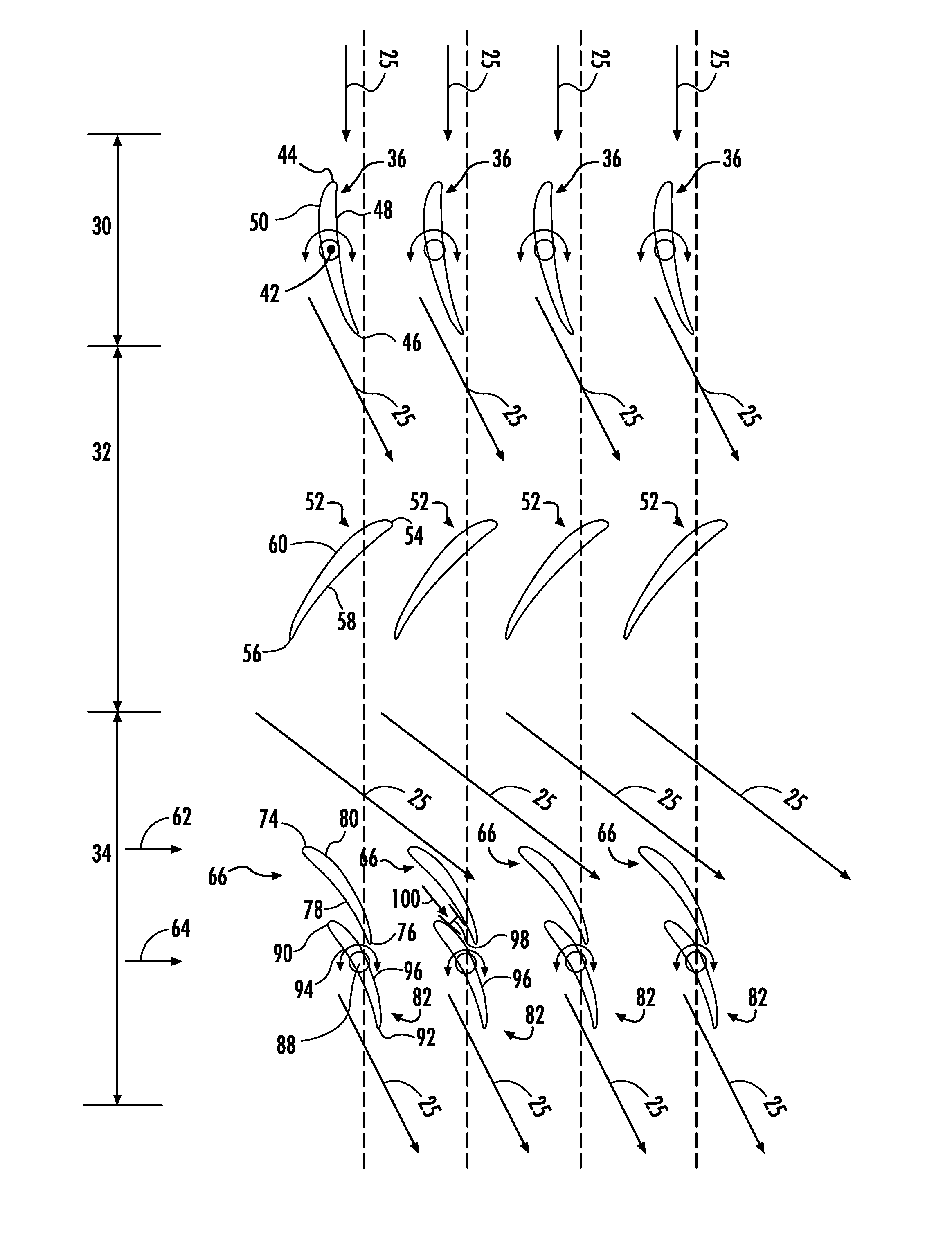
[0009]The present invention may also include a method for improving compressor performance during part-load operation. The method generally includes drawing air into an inlet of the compressor. The air is directed through a closed stage of inlet guide vanes. The air is then directed through a stage of rotor blades and through a row of leading guide vanes. The air is then directed through a closed row of trailing guide vanes.

Problems solved by technology

However, closure of the inlet guide vanes and the variable stator vanes during part-load operation may result in a choked flow condition on the inlet guide vanes and, in particular at the variable stator vanes.
As a result, a passage shock may form on a pressure side of the variable stator vanes, thereby reducing compressor efficiency at the part-load operating condition.

Method used


Image

  • System and method for improving gas turbine performance at part-load operation
  • System and method for improving gas turbine performance at part-load operation
  • System and method for improving gas turbine performance at part-load operation

Examples


Embodiment Construction

[0017]Reference will now be made in detail to present embodiments of the invention, one or more examples of which are illustrated in the accompanying drawings. The detailed description uses numerical and letter designations to refer to features in the drawings. Like or similar designations in the drawings and description have been used to refer to like or similar parts of the invention. As used herein, the terms “first”, “second”, and “third” may be used interchangeably to distinguish one component from another and are not intended to signify location or importance of the individual components. In addition, the terms “upstream” and “downstream” refer to the relative location of components in a fluid pathway. For example, component A is upstream from component B if a fluid flows from component A to component B. Conversely, component B is downstream from component A if component B receives a fluid flow from component A.

[0018]Each example is provided by way of explanation of the invent...


PUM


Abstract

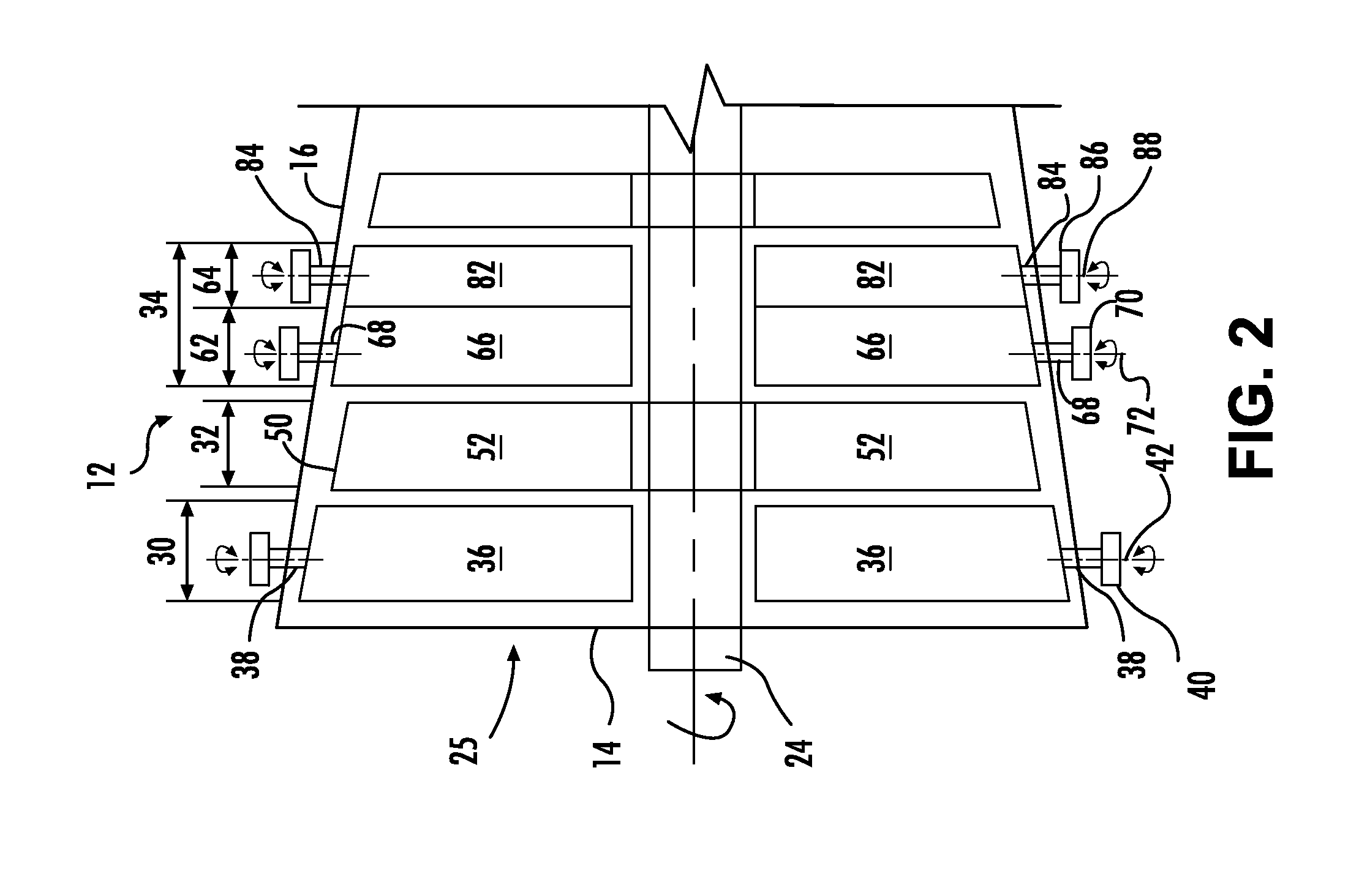
A compressor section of a gas turbine generally includes a stage of inlet guide vanes positioned adjacent to an inlet of the compressor section and a stage of rotor blades disposed downstream from the inlet guide vanes. A stage of stator vanes is positioned downstream from the stage of rotor blades. The stage of stator blades includes a row of leading guide vanes having a trailing edge. A row of trailing guide vanes coupled to an actuator is disposed between two corresponding adjacent leading guide vanes. Each of the trailing guide vanes includes a trailing edge. The leading edge of each trailing guide vane is disposed upstream of the trailing edge of a corresponding leading guide vane when the trailing guide vane is in an open position and downstream from the trailing edge of the corresponding leading guide vane when the trailing guide vane is in a closed position.

Description

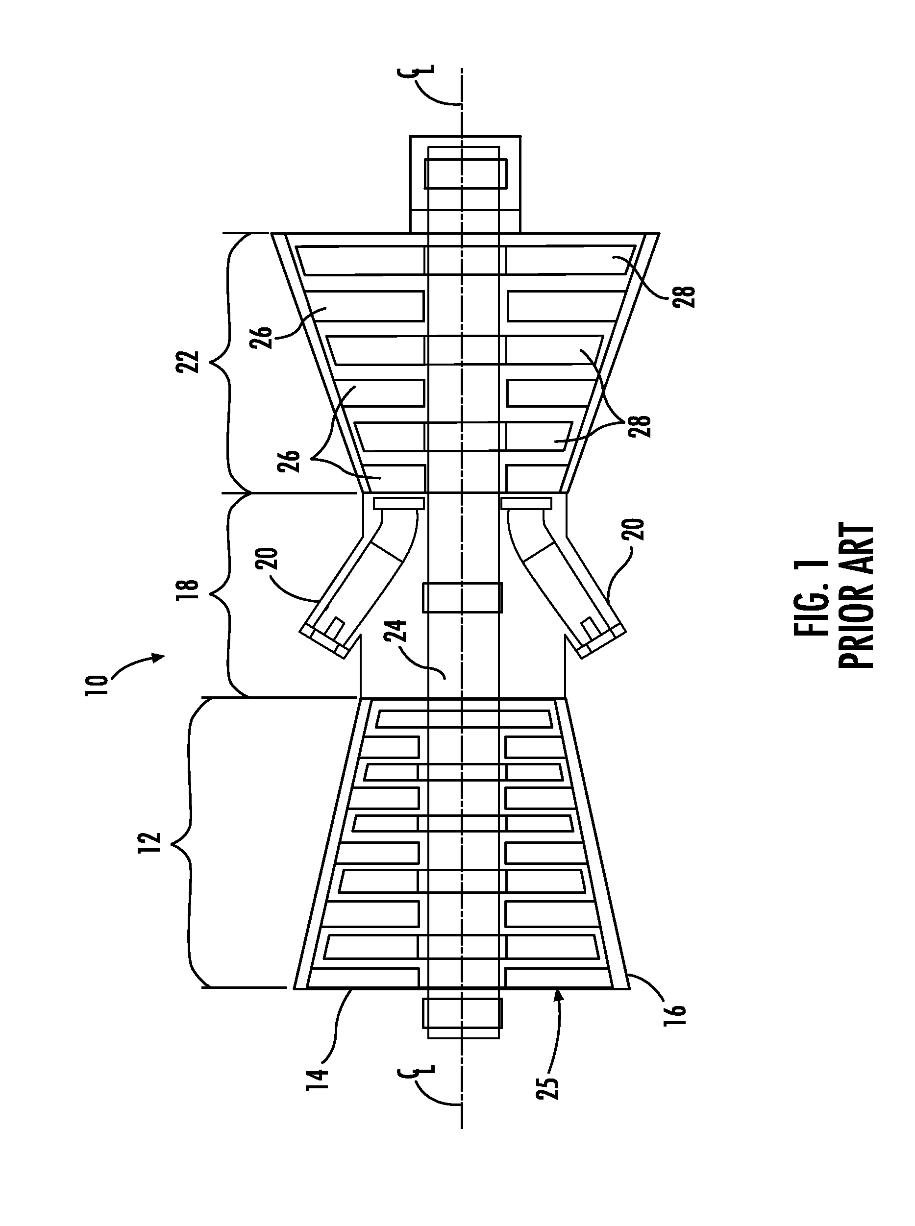
FIELD OF THE INVENTION[0001]The present invention generally involves a compressor of a gas turbine. More particularly, the invention relates to improving the efficiency of the compressor at a part-load operating condition.BACKGROUND OF THE INVENTION[0002]Gas turbines are widely used in industrial and power generation operations. A typical gas turbine may include a compressor section, a combustor downstream from the compressor section, and a turbine section downstream from the combustor. A working fluid such as ambient air flows into the compressor section where it is compressed before flowing into the combustor. The compressed working fluid is mixed with a fuel and burned within the combustor to generate combustion gases having a high temperature, pressure, and velocity. The combustion gases flow from the combustor and expand through the turbine section to rotate a shaft and to produce work.[0003]In particular gas turbines, the compressor section may include a row of inlet guide van...

Claims


Application Information

Patent Timeline
Patent Type & Authority Applications(United States)
IPC IPC(8): F02C3/06F04D19/00F04D27/00
CPCF02C3/06F04D27/002F04D19/00F01D17/162F05D2260/15F04D27/0246F04D21/00
Inventor CHIU, YA-TIENSTAMPFLI, JOHN DAVIDSELMEIER, RUDOLF
Owner GENERAL ELECTRIC CO
Why Eureka
Try Eureka