Power generating device

Inactive Publication Date: 2014-05-15
SHINSEI SHOWJI
View PDF5 Cites 0 Cited by
  • Summary
  • Abstract
  • Description
  • Claims
  • Application Information

AI Technical Summary

Benefits of technology

[0007]The present invention can provide a power generating device having a small rotatio

Problems solved by technology

However, in a conventional power generating device in which a pole of a permanent magnet and a winding core of a coil face each other as disclosed in Patent Document 1, the ro

Method used


Image

  • Power generating device
  • Power generating device
  • Power generating device

Examples


Embodiment Construction

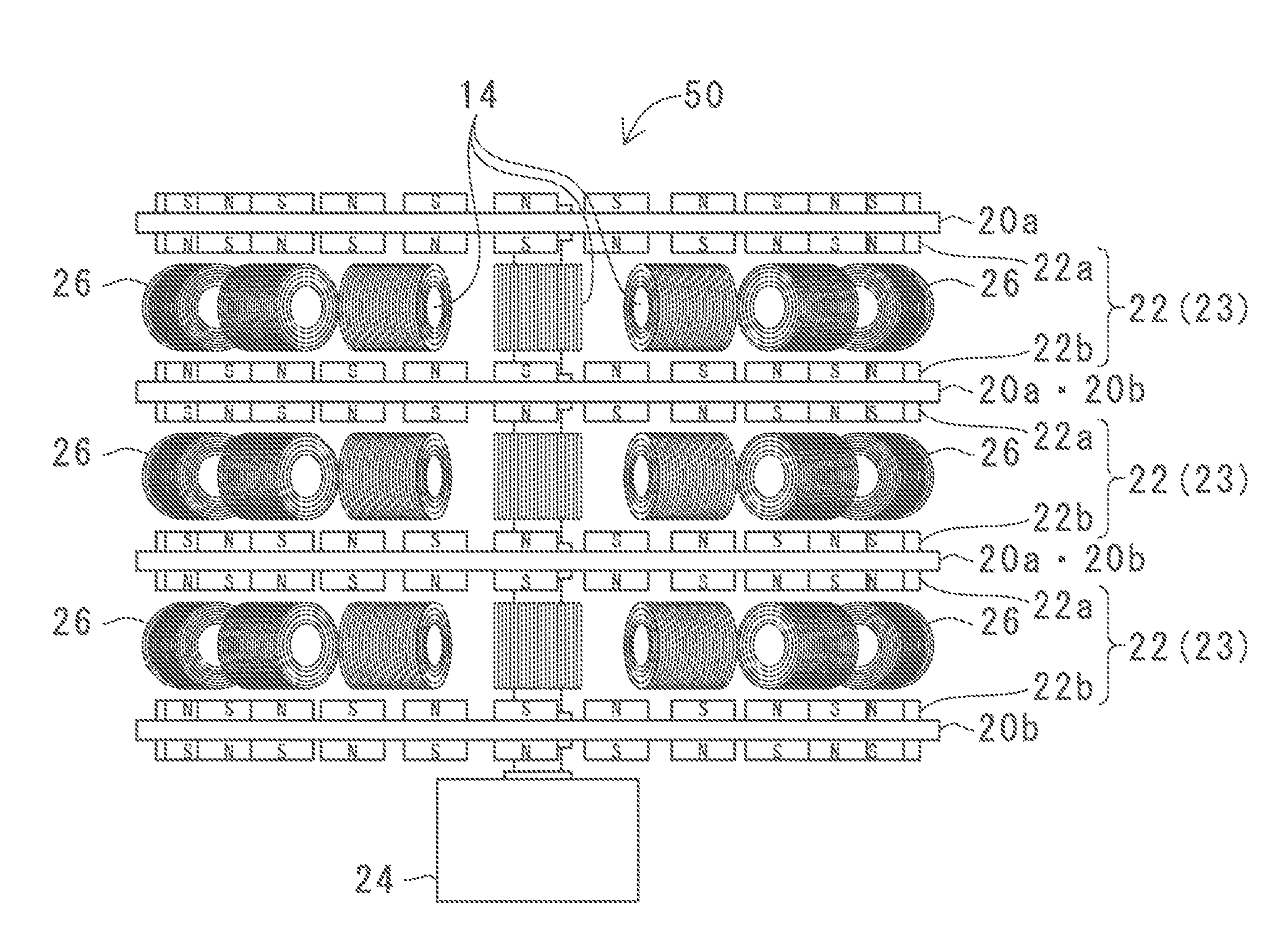
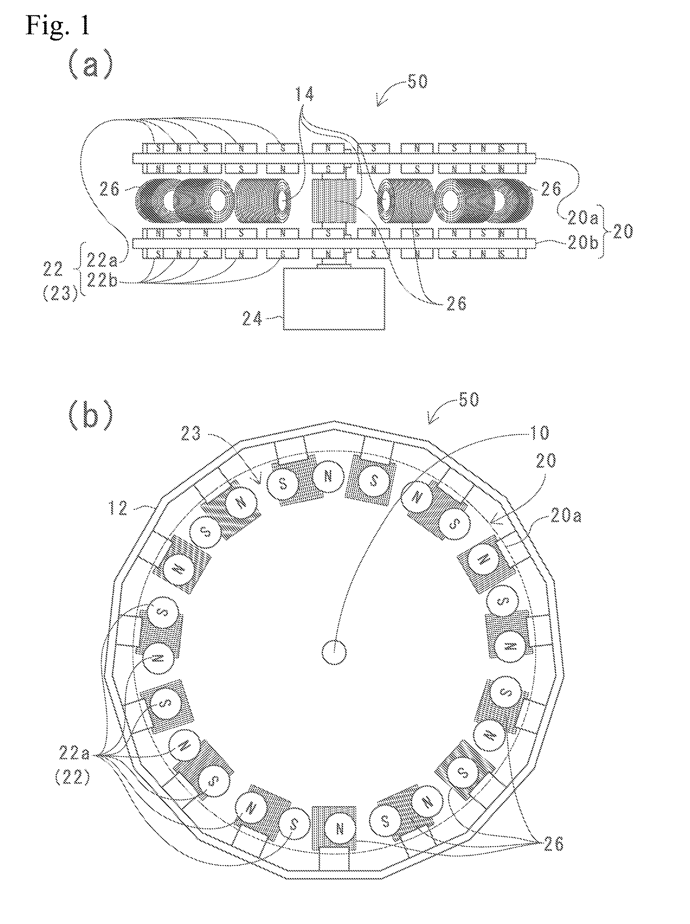
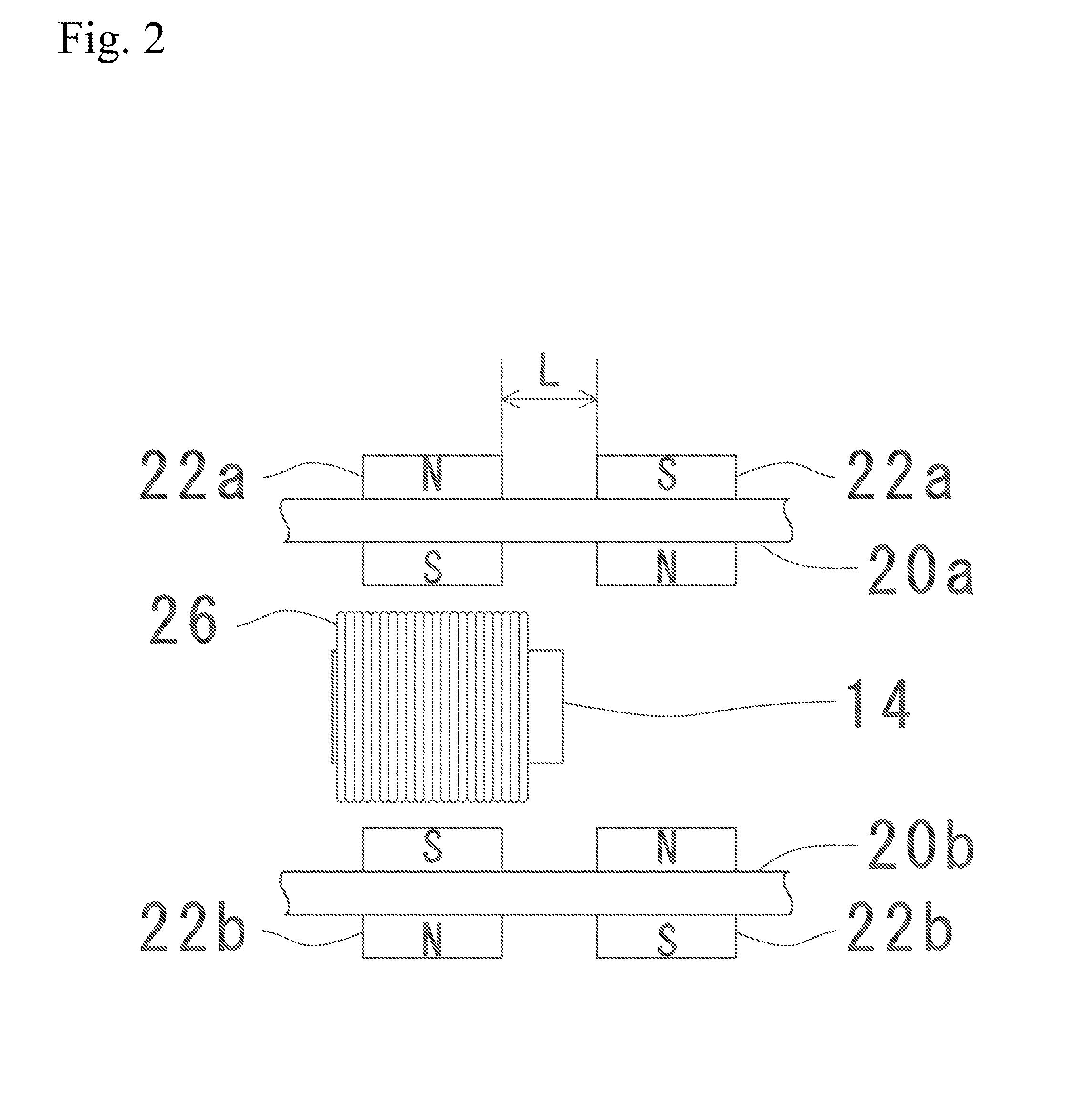
[0014]A power generating device according to the present invention will be described with reference to the drawings. FIG. 1(a) is a side view of a power generating device 50 according to the present invention. FIG. 1 (b) is a top view of the power generating device 50 according to the present invention. Note that a coil holding part 12 is omitted in FIG. 1(a) and FIG. 6 described below. In FIG. 1(b), only an outline of a first rotating plate 20a is indicated by a broken line. In addition, electric wirings are omitted in the figures other than FIG. 5.

[0015]The power generating device 50 according to the present invention has: a first rotating plate 20a and a second rotating plate 20b provided at a predetermined interval and rotating together; a rotating part 20 mainly constituted by the first rotating plate 20a and the second rotating plate 20b; magnet pairs 22 constituted by two permanent magnets 22a and 22b; a magnetic part 23 constituted by the magnet pairs 22 concentrically provi...


PUM


Abstract

To provide a power generating device having a low rotational resistance to a power generation amount and having high conversion efficiency. [Solution] The power generating device (50) of the present invention forms magnetic field lines in a lateral direction between a first rotating plate (20a) and a second rotating plate (20b) and moves the magnetic field lines with respect to coils (26) oriented in the lateral direction, so that it is possible to reduce the difference between sparse and dense magnetic field lines in comparison with conventional power generating devices. Therefore, although the variation of the magnetic field in the coils (26), which is caused by the rotation, is small, the rotational resistance is reduced and the force required for the rotation can be reduced by an amount of the reduced resistance. This can increase the conversion efficiency.

Description

TECHNICAL FIELD[0001]The present invention relates to a power generating device having high conversion efficiency.BACKGROUND ART[0002]In a conventional brushless power generating device using a permanent magnet, as shown in the invention disclosed in, for example, Patent Document 1, a pole of the permanent magnet and a winding core of a coil are generally arranged opposite to each other.PRIOR ARTPatent Document[Patent Document 1] Japanese Published Unexamined Patent Application No. 2009-195051 SUMMARY OF THE INVENTIONProblem(s) to be Solved by the Invention[0003]However, in a conventional power generating device in which a pole of a permanent magnet and a winding core of a coil face each other as disclosed in Patent Document 1, the rotational resistance becomes large at starting or generating power due to strong magnetic force applied to the coil, and there is a limitation on conversion efficiency obtained.[0004]In view of the above problem, the present invention has been made and a...

Claims


Application Information

Patent Timeline
IPC IPC(8): H02K1/06
CPCH02K1/06H02K21/24H02K16/00
Inventor MATUSHITA, KIYOHIKONOGAMI, MASAKAZU
Owner SHINSEI SHOWJI
Why Eureka
Try Eureka