Cutter wheel holder unit

A technology for cutter wheel holders and scoring wheels, which is applied to electrical components, manufacturing tools, glass manufacturing equipment, etc., and can solve the problems of reduced rotational resistance and difficulty in stability of scoring wheels

Inactive Publication Date: 2014-03-26
MITSUBOSHI DIAMOND IND CO LTD
View PDF7 Cites 13 Cited by
  • Summary
  • Abstract
  • Description
  • Claims
  • Application Information

AI Technical Summary

Problems solved by technology

Therefore, there is a disadvantage that it is difficult to hold the scor...

Method used


Image

  • Cutter wheel holder unit
  • Cutter wheel holder unit
  • Cutter wheel holder unit

Examples


Embodiment Construction

[0040] In order to further illustrate the technical means and effects that the present invention takes to achieve the intended purpose of the invention, below in conjunction with the accompanying drawings and preferred embodiments, the specific implementation, structure, features and features of the cutter wheel holder unit proposed according to the present invention will be described below. Efficacy, detailed as follows.

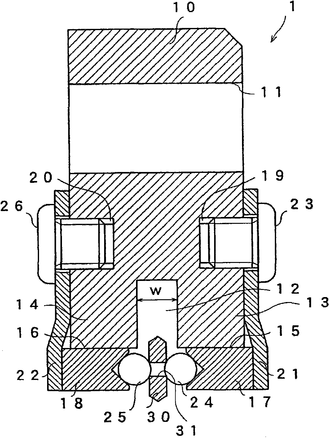
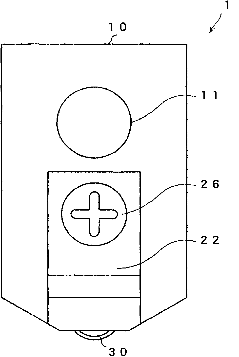
[0041] The cutter wheel holder unit according to the first embodiment of the present invention will be described using the drawings. figure 2 is a sectional view of the wheel holder unit, image 3 is its front view. The wheel holder unit 1 has a wheel holder 10 and a scoring wheel 30 , and holds the scoring wheel 30 rotatably at the lower end of the wheel holder 10 . Cutter wheel holder 10, as in Figure 4 As shown in the front view, it is a cuboid-shaped member with the lower left and right parts cut, and has a through hole 11 for fixing the cutter whe...


PUM


Abstract

The invention relates to a cutter wheel holder unit, by means of which a scribing wheel can be kept stably in position and the linearity of a scribed line is improved. According to the technical scheme of the invention, a scribing wheel (30) is in the form of a circular plate and the center of the scribing wheel (30) is provided with a through hole (31). The outer peripheral part of the circular plate is provided with a v-shaped cutter front end. A cutter wheel holder body (10) is provided with a holder groove (12) of a certain width and used for the insertion of the scribing wheel (30), and a pair of supporting parts (13, 14). Ball holders (17, 18) are inserted into the through holes (15, 16) of the supporting parts (13, 14). By means of a pair of balls (24, 25) and the ball holders (17, 18), the scribing wheel (30) is clamped into the holder unit in a freely rotating manner.

Description

technical field [0001] The present invention relates to a wheel holder unit for holding a scribing wheel for forming scribe lines on a brittle material substrate. Background technique [0002] A scribing device is used for scribing and breaking a brittle material substrate into a desired size. The scribing device includes a wheel holder unit on a scribing head facing the brittle material substrate. figure 1 , is a sectional view of a known wheel holder unit disclosed in Patent Document 1. The wheel holder unit 100 has a wheel holder body 110 , a scoring wheel 120 , and a pin 130 , and the scoring wheel 120 is attached to the wheel holder body 110 . [0003] Such as figure 1 As shown, a holder groove 111 and a pin hole 112 are formed at the lower part of the cutter wheel holder 110 . The scoring wheel 120 is a disc-shaped member, has a through hole penetrating through the center of two circular side surfaces, and has a V-shaped blade tip along the outer periphery of the s...

Claims


Application Information

Patent Timeline
IPC IPC(8): B26D1/14B26D7/26
CPCB28D5/0082C03B33/027C03B33/037H01L21/67092
Inventor 林弘义
Owner MITSUBOSHI DIAMOND IND CO LTD
Why Eureka
Try Eureka