Rigidly mounted tracking solar panel and method

Inactive Publication Date: 2017-04-13
THE BOEING CO
View PDF4 Cites 4 Cited by
  • Summary
  • Abstract
  • Description
  • Claims
  • Application Information

AI Technical Summary

Benefits of technology

[0007]The present disclosure describes a solar panel that employs plural lenses rigidly mounted to a framework. Flexible supports depend from plural lenses and hold a movable panel in spaced relation to the plural lenses. The lenses focus the sunlight, as it moves with the moving sun, onto the movable panel and, in particular, onto photovoltaic material on the movable panel. The focusing of sunlight on photoelectric material enables higher conversion efficiencies at lower material cost. The array of lenses is oriented east-west and tilted to match the sun's tilt angle with respect to the earth. Tracking of the sun's movement through the seasons is thus reduced and can be further accommodated by movin

Problems solved by technology

There are disadvantages to fixed, flat silicon solar panels.
In the case of power plants, land requirements for solar collectors quickly become the dominant cost.
Finally, most solar panels are made overseas so supplies of new and replacement panels may be subject to international stability issues and currency fluctuations.
While solar panel tracking syste

Method used


Image

  • Rigidly mounted tracking solar panel and method
  • Rigidly mounted tracking solar panel and method
  • Rigidly mounted tracking solar panel and method

Examples


Example

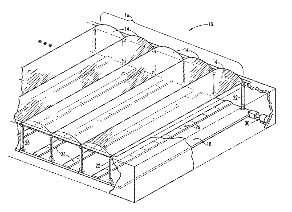
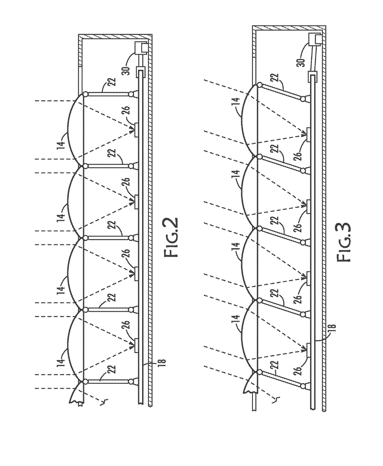
[0026]The solar panel as disclosed may be in the form of a solar panel 10 that may be rigidly mounted to a solid surface with the proper orientation and tilt, and commence to automatically track the sun's movement and to optimize the collection efficiency of the photovoltaic material being used. Solar panel 10 may be thin: 1.5 cm-2.5 cm thick, for example, and scalable. A solar panel 10 may be a square meter, for example, and light-weight. It may use less photovoltaic material so using higher efficiency concentrator photocell materials becomes cost-effective. Its lenses can be made of any optical glass or optical plastic and may be configured as Fresnel lenses.

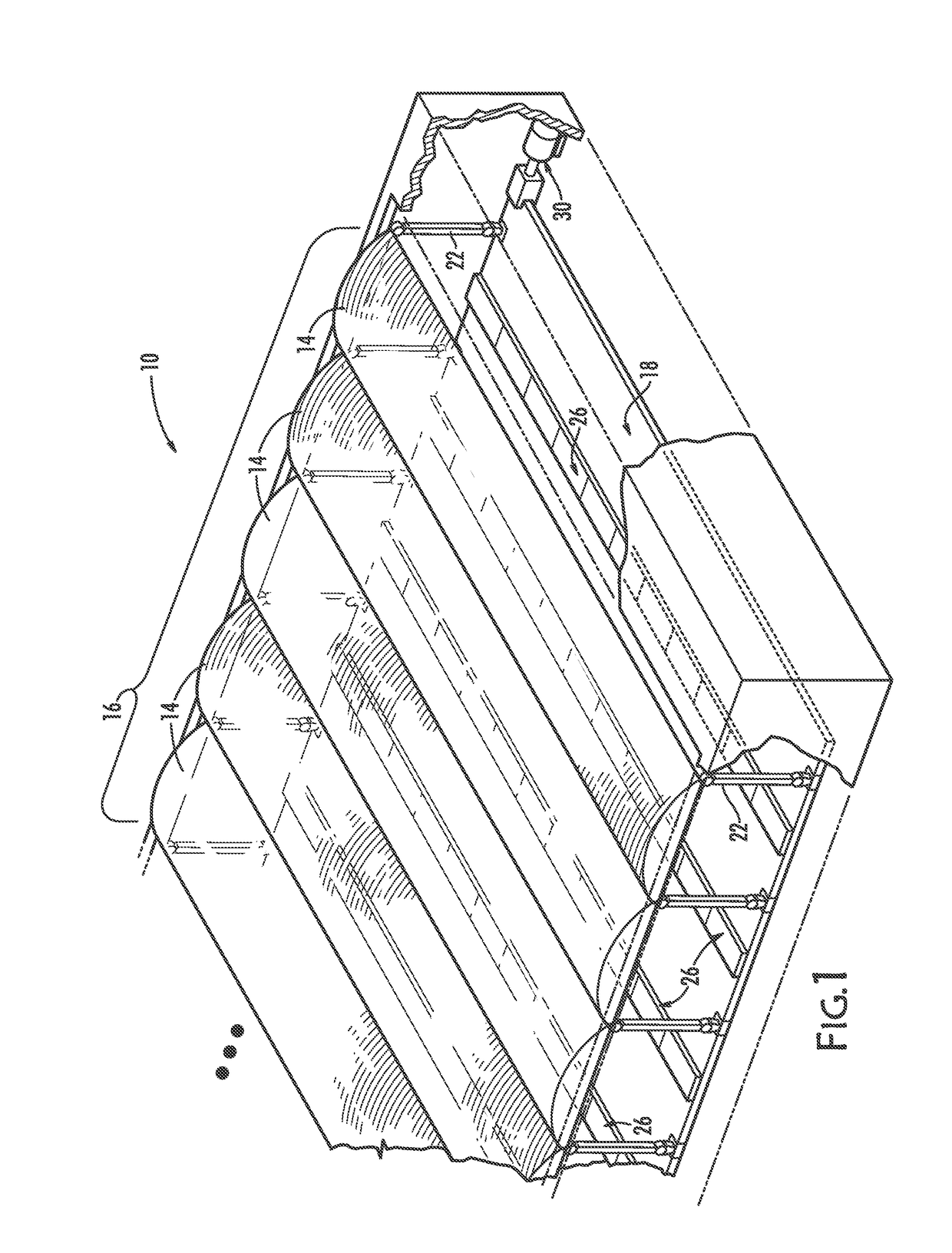
[0027]FIG. 1 is a perspective view of a solar panel 10 comprising plural lenses 14, arranged in an array 16 and supporting a movable panel 18 by flexible supports 22. Lens 14 in array 16 is shown as cylindrical in this illustration and has an axis of symmetry parallel with the long dimension of lens 14. In use, panel 18 would ...


PUM


Abstract

A rigidly mountable solar panel includes lenses supported above a movable panel to focus sunlight onto photovoltaic material carried on the movable panel. Flexible supports space the movable panel at the focal points of the lenses, and a servo-mechanism enables movement of the movable panel to adjust position as the focal point moves with the sun. A light detector on the movable panel, sensing movement of the focal point signals the servo-mechanism to adjust the position of the movable panel automatically, thereby tracking the sun's movement. Concentrating sunlight on photovoltaic material selected to have higher conversion efficiency increases output. Segmenting the photovoltaic material so the output of the segments can be combined in a series-parallel relationship and using mirrors on the ends of the movable panel to reflect sunlight onto the segments allows electricity that is generated by the photovoltaic material to be more uniform during daylight.

Description

TECHNOLOGICAL FIELD[0001]The present disclosure relates generally to the solar panels. More specifically, the present disclosure relates to solar panels that track the movement of the sun.BACKGROUND[0002]Most solar panels that convert the sun's radiation into electric energy use fixed flat-panels of silicon. Silicon is the photovoltaic material of choice because its properties are well known and it is cheap, readily available in the quantities needed, durable and reliable. Silicon is also a single-junction photovoltaic material so it is not affected by changes in the spectral distribution; its output depends on the integrated power density within the limits of its absorption range. Flat panels of silicon are simple to make and install in an outdoor environment.[0003]There are disadvantages to fixed, flat silicon solar panels. Silicon has a relatively low conversion efficiency, typically 18% to 20% and theoretically not to exceed 30%. Because of this relatively low conversion efficie...

Claims


Application Information

Patent Timeline
IPC IPC(8): H02S20/32H02S40/22
CPCH02S40/22H02S20/32F24S30/40F24S2030/11H02S40/32F24S23/30F24S2020/186H01L31/048H01L31/0543Y02E10/47Y02E10/52H01L31/042H02S30/00Y02E10/50
Inventor JUNGWIRTH, DOUGLAS R.
Owner THE BOEING CO
Why Eureka
Try Eureka