
Portable Battery Charger with Inductive Charging

Inactive Publication Date: 2014-05-15
POWERSTICK COM
View PDF8 Cites 63 Cited by
  • Summary
  • Abstract
  • Description
  • Claims
  • Application Information

AI Technical Summary

Benefits of technology

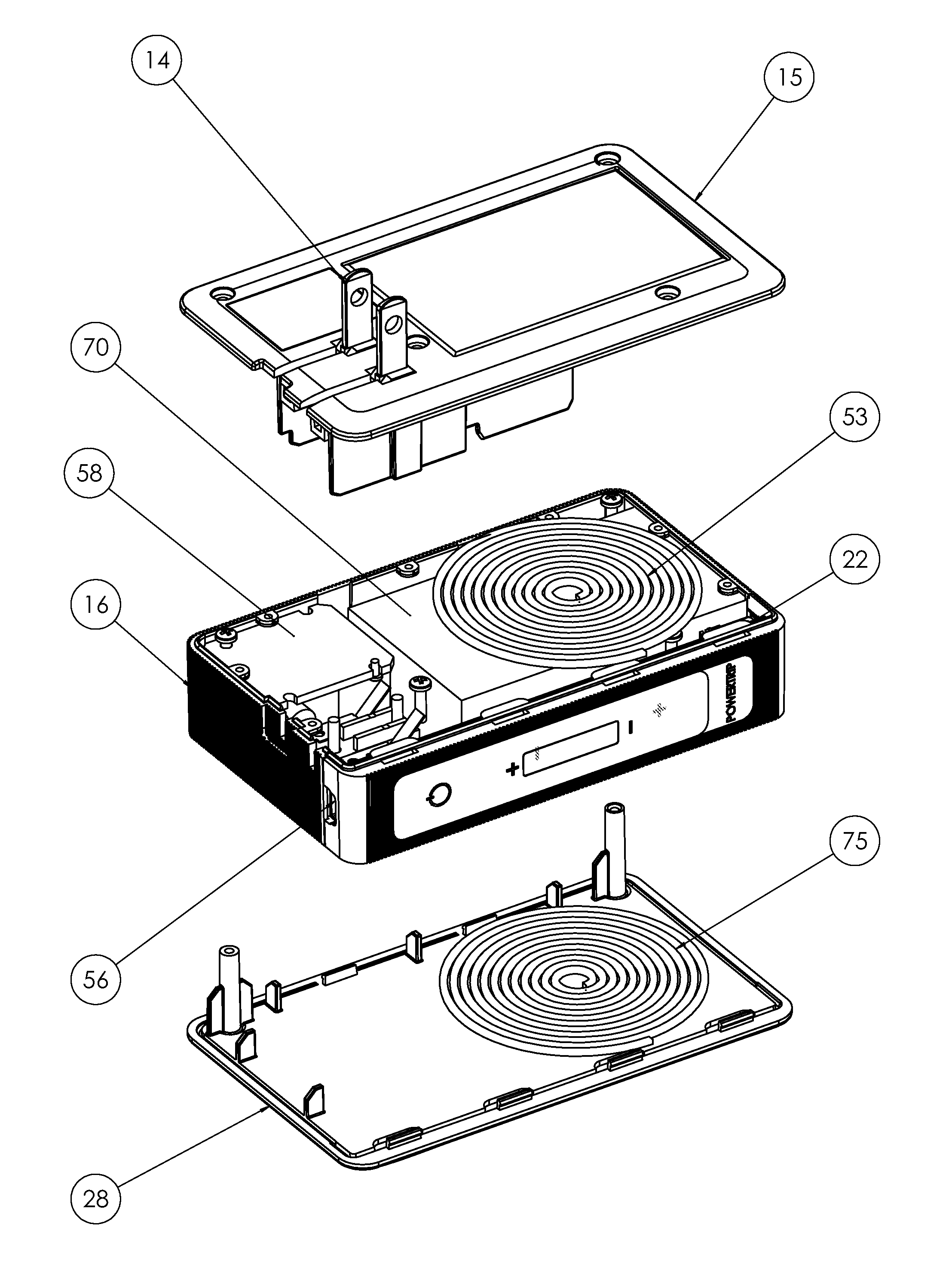
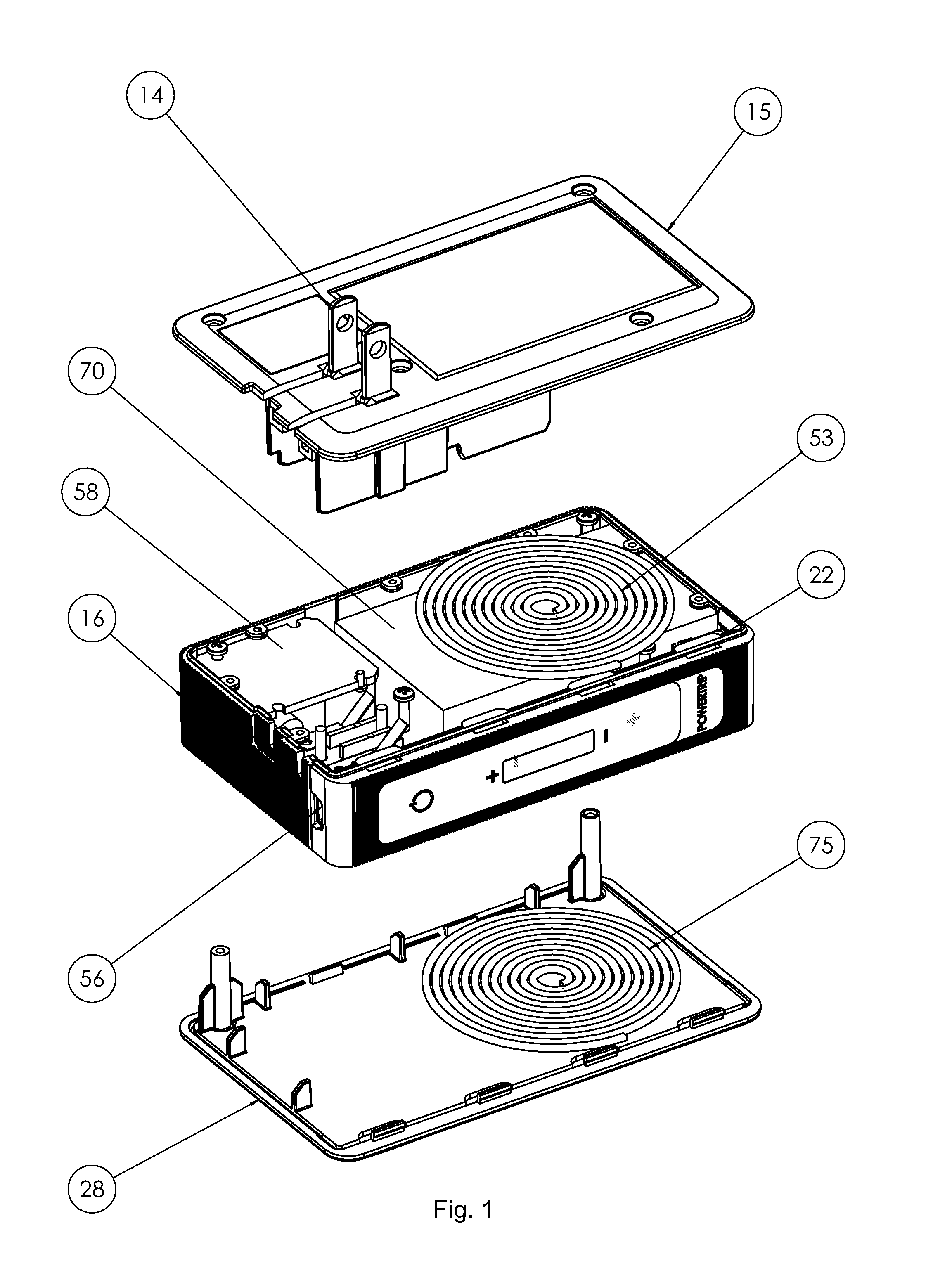
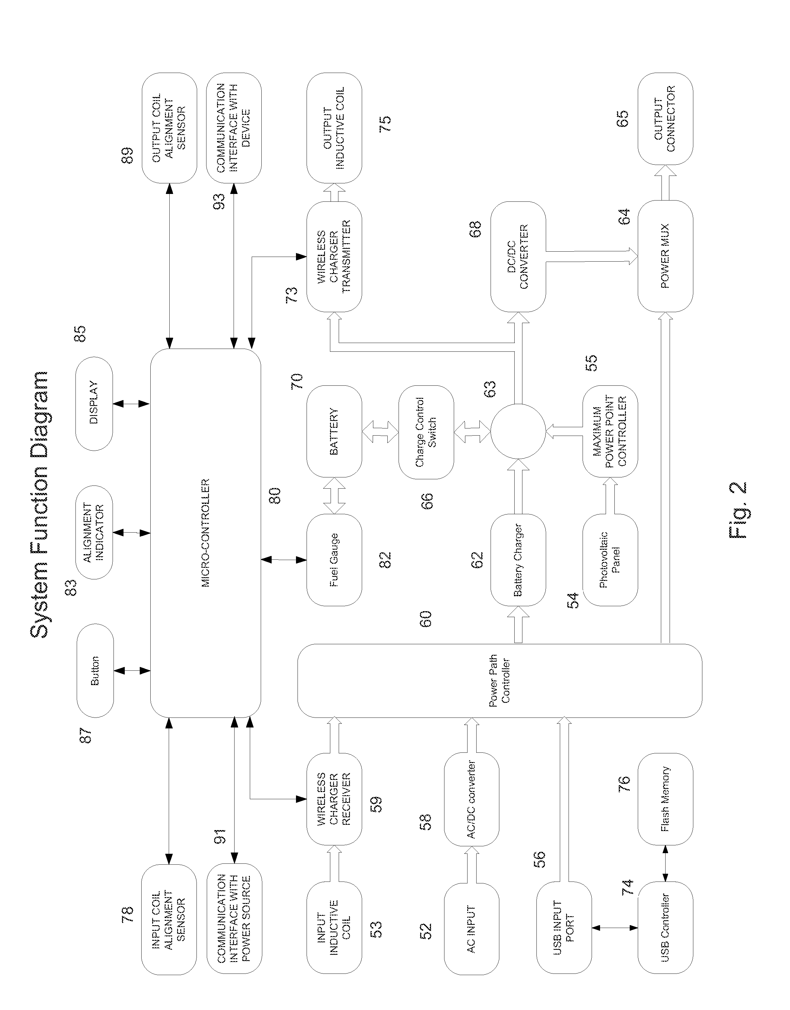
The patent describes a portable battery charger with an inductive charging system. The charger has a housing, output inductive coil, and battery. The output inductive coil transmits power to the portable device, which has its own coil to receive the power. The charger can also be used as a wireless charger to transmit power. The charger operates at the battery voltage, and a switch can be used to select output or input functions. A magnet may be used to align the output coil with the portable device's coil, and an alignment indicator and sensor provide information on the alignment. The method involves aligning the portable device's coil with the charger's coil and commencing inductive charging, followed by determining the efficiency of the charging and adjusting the portable device's position on the charger. The efficiency can be compared to a maximum efficiency, and feedback can be provided through an alignment indicator. In summary, the patent presents a portable battery charger with a unique design that utilizes inductive charging technology.

Problems solved by technology

Connectors have little to no loss in transmission, however they are subject to damage and wear and tear, as they are composed of movable parts.
Further, connectors are proprietary and, although common within a manufacturer's line, are not easily used across different manufacturers of devices.
Considering a universal charger, if the correct adapter plug is not available then the charger will be useless.

Method used


Image

  • Portable Battery Charger with Inductive Charging
  • Portable Battery Charger with Inductive Charging
  • Portable Battery Charger with Inductive Charging

Examples


examples

[0040]In one embodiment, the battery is 5700 mAh. An empty battery can be charged within 8 hours by means of the AC power input, while charging by USB input takes more than 12 hours. Performance may be enhanced by increasing the AC / DC converter 58 from a 3.5 W to a 7.5 W rating, and to insert a battery charger 62 that is more efficient, for example moving from a linear charger to a switching charger. To illustrate the example, the linear charger, while its input and output current are same (1.0 A), the voltage difference between input voltage (5V) and the output voltage (battery voltage 3-4.2V) will be on the linear charger and wasted as heat. The average charging efficiency is only about 70%. The switching charger has an efficiency of more than 90%, and is able to vary the voltage and current. If the input to the charger is 5V and 1 A, and the battery is at 3V, then 3V and 1.5 A may be provided to the battery 70 by the switching charger, resulting in faster charging than the linear...


PUM


Abstract

A portable battery charger with inductive charging has a housing, an output inductive coil beneath the surface of the housing to transmit power to a portable device also having a coil therein, and a battery within the housing connected to the output coil, wherein the output coil operates at the battery voltage and transmits power from the battery to the portable device. The charger may also have an input inductive coil beneath the surface of the housing to receive power from a source, and transmit the power to the battery, and the output coil and the input coil may be the same coil. A method of charging the battery of a portable device comprises the steps of aligning the input coil of a portable device adjacent to with an output coil of a charger using magnets positioned near the respective coils, and inductively charging the device battery without connecting the device to the charger.

Description

FIELD OF THE INVENTION[0001]The invention relates to battery chargers having inductive charging capability for recharging portable devices.BACKGROUND[0002]Since their early development portable electronic devices like cell phones have used AC / DC adapters to charge their batteries from household AC power. More and more, USB connections are also used to charge portable devices using a DC current of approximately 5V, as well the USB can be used to exchange data between the USB source and the portable device. Especially convenient is a portable charger containing a battery, which can be charged from an AC or USB source and then carried along for later charging of a device when away from the source.[0003]This charging has required a connector, in order to positively connect the device with the charger, so as to transfer energy. Connectors have little to no loss in transmission, however they are subject to damage and wear and tear, as they are composed of movable parts. Further, connector...

Claims


Application Information

Patent Timeline
IPC IPC(8): H02J7/00
CPCH02J50/10H02J50/90H02J7/00309H02J7/00304H02J7/00308H02J7/0029H02J50/12
Inventor ZHU, ZUOHANG
Owner POWERSTICK COM
Learn More