
Ophthalmic imaging apparatus, control method for ophtalmic imaging apparatus, and storage medium

a technology of ophtalmic imaging and control method, which is applied in the field can solve the problems of inability to dynamically deactivate functions, the item cannot be changed, and the function cannot be dynamically deactivated during imaging operations, so as to improve the operability of ophthalmic imaging apparatus

Active Publication Date: 2014-05-15
CANON KK
View PDF3 Cites 11 Cited by
  • Summary
  • Abstract
  • Description
  • Claims
  • Application Information

AI Technical Summary

Benefits of technology

This patent describes a way to make it easier for people to use an eye imaging machine for eye exams.

Problems solved by technology

However, when capturing an image of a fundus, there are cases where an examiner changes the alignment state and the focus state based on the state of the eye to be examined after the alignment and focus have been automatically adjusted, and thus the fundus cameras disclosed in Japanese Patent No. 3490796 and Japanese Patent Laid-Open No. 2005-160549 have a problem in that these items cannot be changed because the imaging is carried out automatically.
However, it is necessary to activate or deactivate the respective functions before imaging operations are started, and thus there is a problem in that once imaging operations have been commenced with the autofocus function and the auto shoot function active, those functions cannot be dynamically deactivated after judging the state of the eye to be examined from an observation image of that eye, whose image is to be captured.
The ophthalmic imaging apparatus disclosed in Japanese Patent Laid-Open No. 2009-172157 is configured having pre-set conditions that deactivate the autofocus function and the auto shoot function operations, where the autofocus function and the auto shoot function are deactivated when those conditions are met; however, this configuration requires the conditions for deactivating the operations to be set in advance, and there is thus a problem in that the functions cannot be dynamically deactivated during imaging operations.
However, Japanese Patent No. 3490796, Japanese Patent Laid-Open No. 2005-160549, and Japanese Patent Laid-Open No. 2009-172157 have problems in that the autofocus function and the auto shoot function cannot be changed from inactive to active during imaging operations.
Accordingly, with conventional ophthalmic imaging apparatuses, it is difficult to carry out operations that meet an examiner's needs.

Method used


Image

  • Ophthalmic imaging apparatus, control method for ophtalmic imaging apparatus, and storage medium
  • Ophthalmic imaging apparatus, control method for ophtalmic imaging apparatus, and storage medium
  • Ophthalmic imaging apparatus, control method for ophtalmic imaging apparatus, and storage medium

Examples


first embodiment

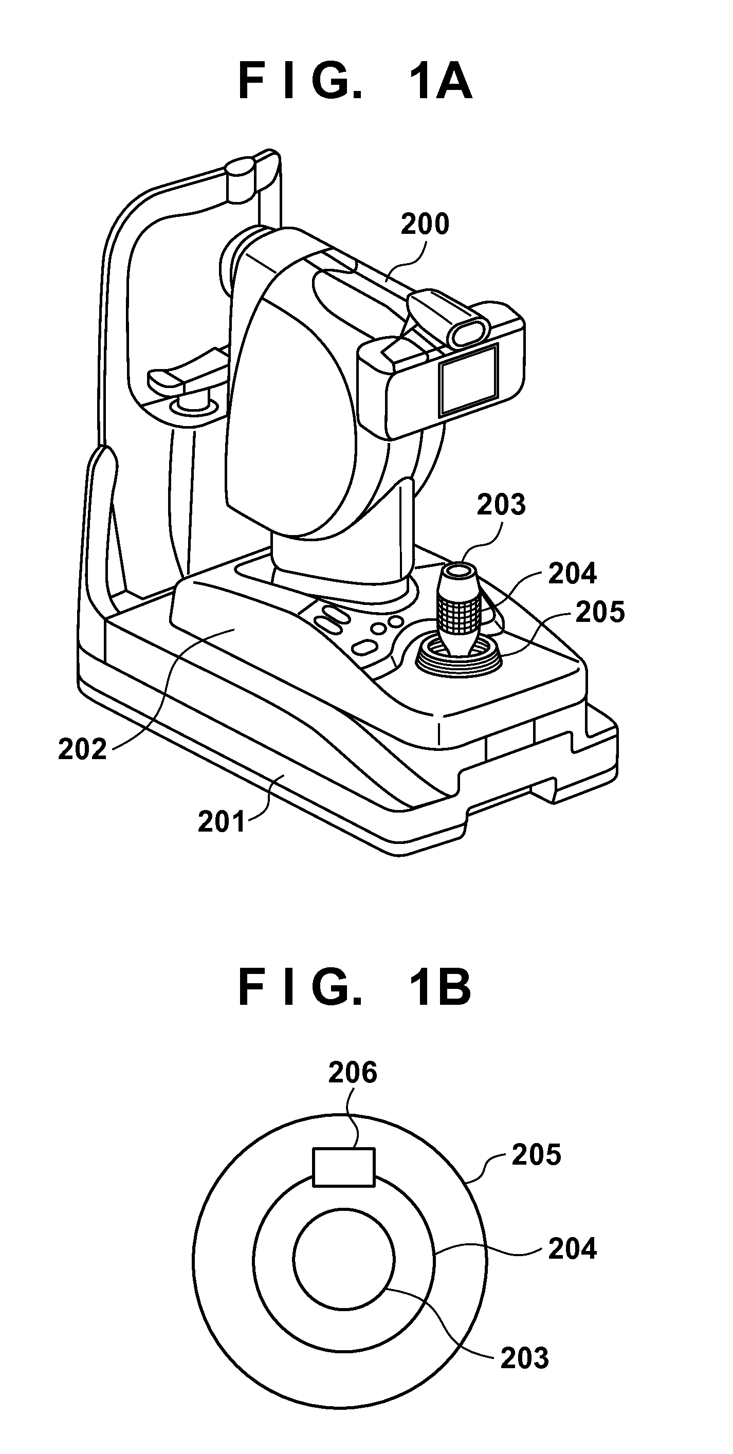
[0036]FIG. 1A is a diagram illustrating an overview of a fundus camera serving as an ophthalmic imaging apparatus embodying the present invention, whereas FIG. 1B is a schematic diagram illustrating the configuration of a focus manipulation portion and a joystick portion illustrated in FIG. 1A.

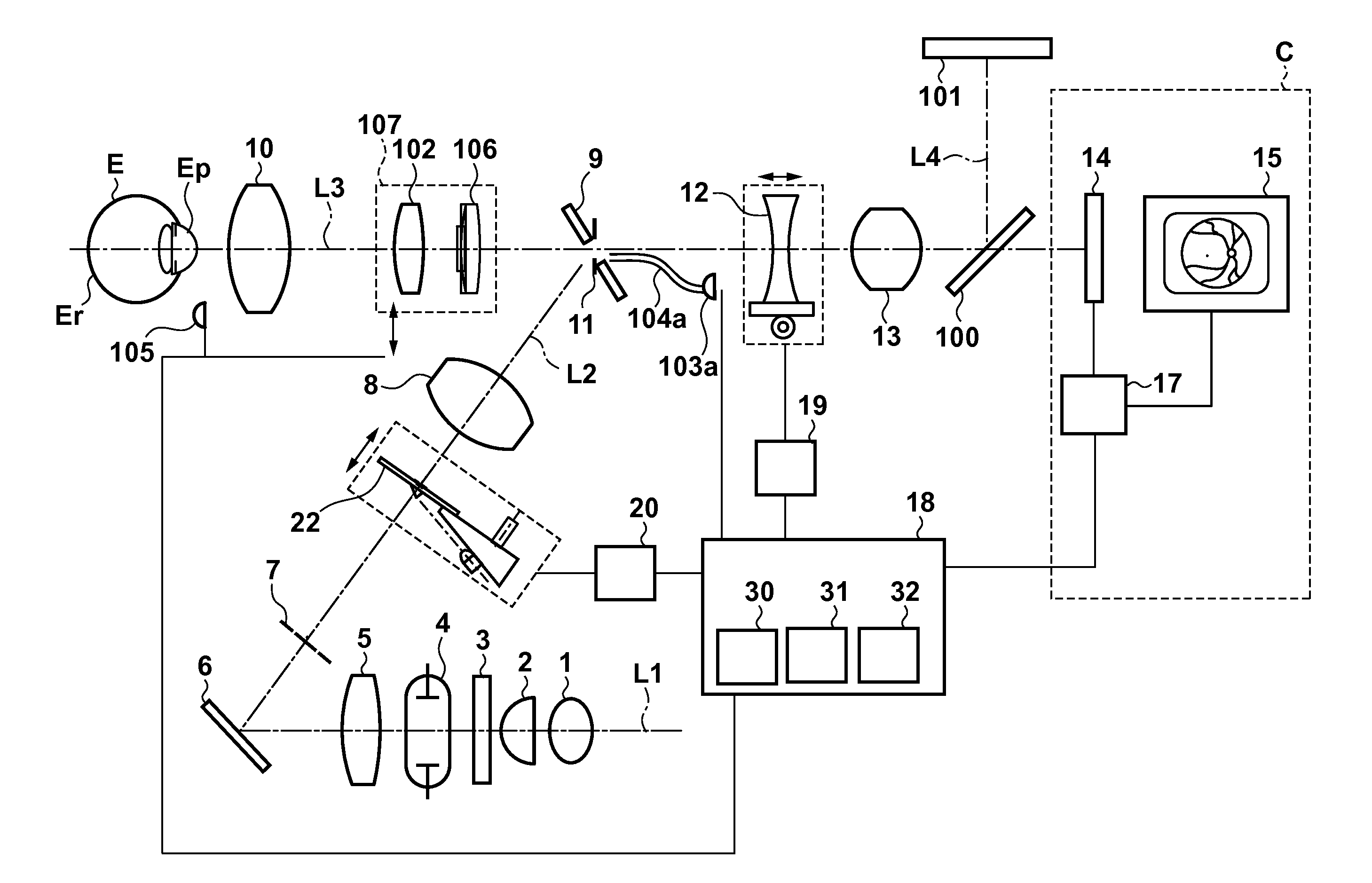
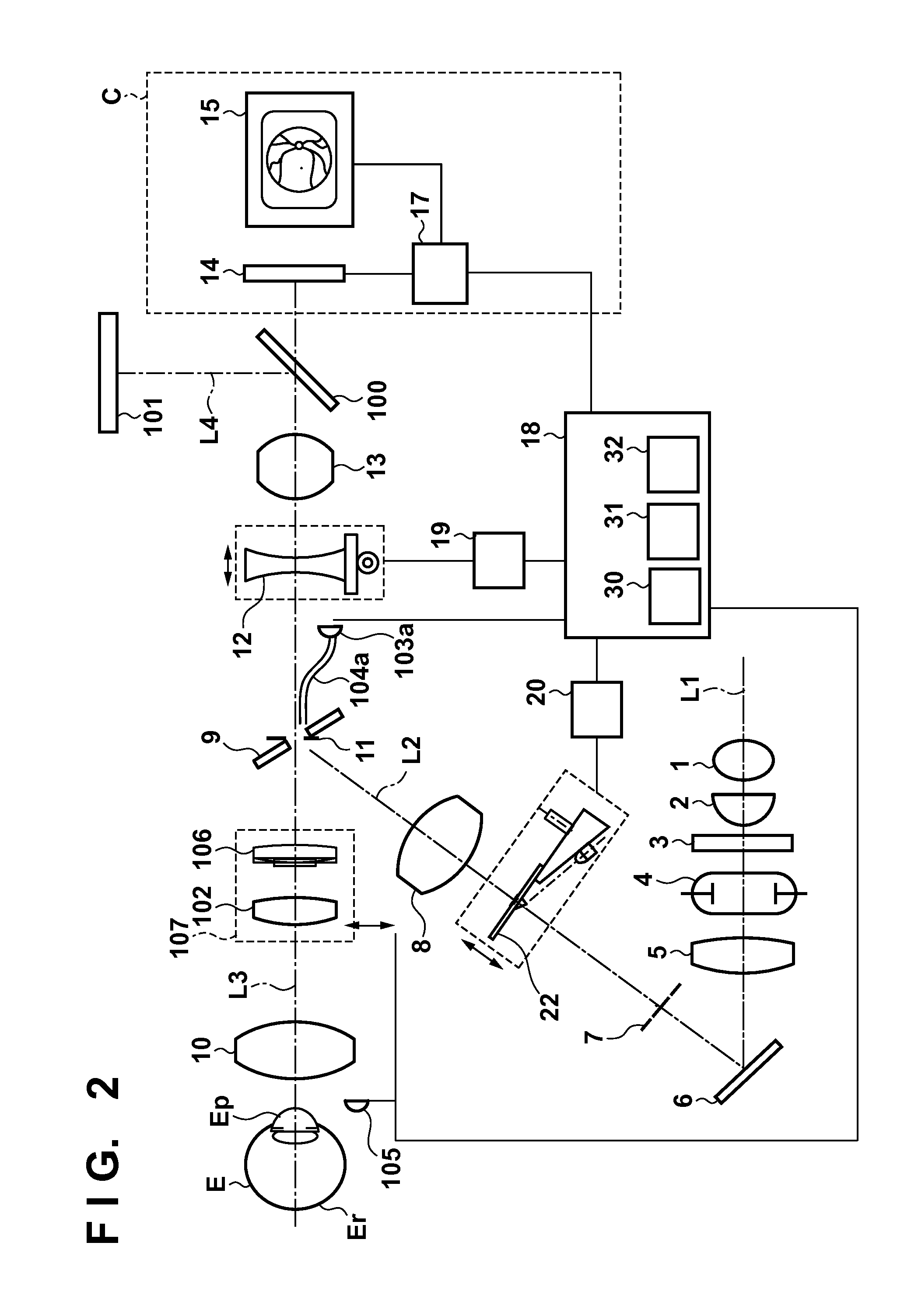
[0037]An optical main body 200 that includes an optical system for observing / imaging an eye to be examined is anchored to a movable stage 202 capable of moving forward / backward and left / right upon a fixed base 201. A joystick 204 including a focus manipulation unit 205, an imaging switch 203, and an alignment toggle switch 206 is provided on the movable stage 202. By operating the joystick 204, an examiner can move the movable stage 202 to a desired position, and by manipulating the focus manipulation unit 205, the examiner can adjust the focal position on an eye to be imaged.

[0038]The imaging switch 203 is configured so as to be depressible in two stages. The functions implemented when the im...


PUM


Abstract

An ophthalmic imaging apparatus having an automatic transition function for transiting from an anterior ocular observation state to a fundus observation state, an autofocus function performed during fundus observation, and an automatic image capturing function performed when fundus alignment is complete, the apparatus comprising: a first control unit configured to control the automatic transition function, the autofocus function, and the automatic image capturing function to be deactivated in response to a first user operation; and a second control unit configured to control the deactivated automatic transition function, autofocus function, and automatic image capturing function to be reactivated in response to a second user operation.

Description

BACKGROUND OF THE INVENTION[0001]1. Field of the Invention[0002]The present invention relates to ophthalmic imaging apparatuses for observing or capturing images of the fundus of an eye to be examined, such as fundus cameras used in ophthalmological clinics, group health examinations, and the like, and further relates to control methods for such ophthalmic imaging apparatuses and storage medium.[0003]2. Description of the Related Art[0004]Fundus cameras that automatically execute alignment operations for aligning a fundus camera optical system with an eye to be examined and focus adjustment operations, in order to simplify those operations, have been proposed in the past (see Japanese Patent No. 3490796 and Japanese Patent Laid-Open No. 2005-160549).[0005]Meanwhile, an ophthalmic imaging apparatus that has an autofocus function, an auto small pupil switching function, and an auto shoot function and that is capable of activating and deactivating these automatic functions individually...

Claims


Application Information

Patent Timeline
Patent Type & Authority Applications(United States)
IPC IPC(8): A61B3/15
CPCA61B3/152A61B3/12A61B3/14
Inventor HARA, HIROSHI
Owner CANON KK
Learn More