Method and apparatus for uplink power control

a power control and uplink technology, applied in power management, wireless communication, wireless commuication services, etc., can solve problems such as error in estimating path loss, uplink power control, and transmission power of the ue cannot be efficiently controlled, and achieve the effect of ensuring the efficiency of power control

Inactive Publication Date: 2014-05-15
FUJITSU LTD
View PDF11 Cites 21 Cited by
  • Summary
  • Abstract
  • Description
  • Claims
  • Application Information

AI Technical Summary

Benefits of technology

[0016]The advantage of the embodiments of the present invention resides in that on the basis of performing original uplink power control according to a path loss estimated based on downlink CRS, the network side estimates a path loss compensation value of UE by triggering RRH UE to transmit aperiodic SRSs, and semi-statically informs the UE, so as to compensate for the inaccuracy of estimation of path loss, thereby ensuring the efficiency of power control.

Problems solved by technology

Among research points regarding the above scenario, one is an issue of uplink power control.
However, in the heterogeneous deployment network scenario shown in FIG. 1, the transmission power of the UE cannot be efficiently controlled in the original method for uplink power control in which path loss is estimated based on a CRS, as multiple low power RRHs and an eNB coexist in one cell in such a scenario.
Therefore, the uplink and the downlink are asymmetrical, and there exists an error in estimating path loss, as the path loss value estimated based on a downlink CRS is not real uplink single-link path loss in the original LTE standard.

Method used


Image

  • Method and apparatus for uplink power control
  • Method and apparatus for uplink power control
  • Method and apparatus for uplink power control

Examples


embodiment 1

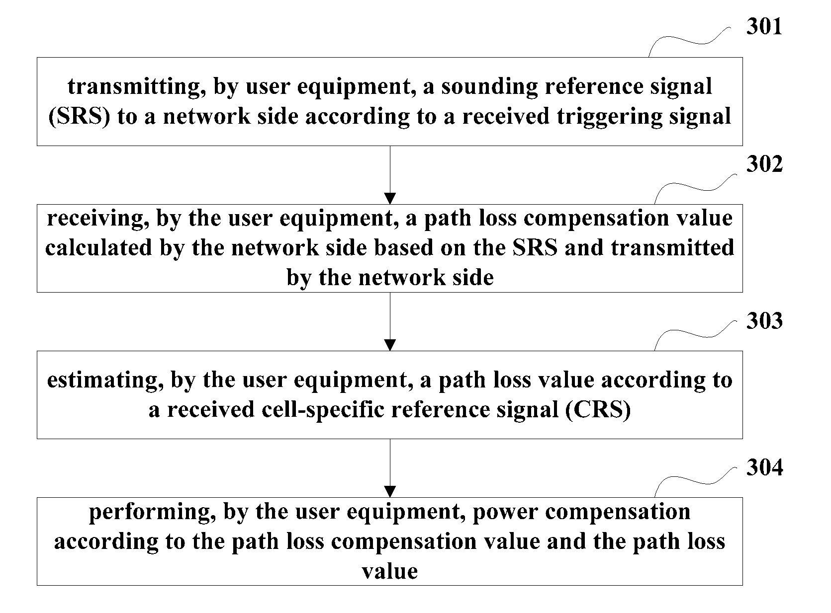
[0030]FIG. 3 is a flowchart of a method for uplink power control provided by an embodiment of the present invention, applicable to UE accessed to a certain RRH in a heterogeneous deployment network scenario of CoMP transmission. Referring to FIG. 3, the method includes:

[0031]step 301: transmitting, by user equipment, a sounding reference signal (SRS) to a network side according to a received triggering signal;

[0032]step 302: receiving, by the user equipment, a path loss compensation value calculated by the network side based on the SRS and transmitted by the network side;

[0033]step 303: estimating, by the user equipment, a path loss value according to a received cell-specific reference signal (CRS); and

[0034]step 304: performing, by the user equipment, power compensation according to the path loss compensation value and the path loss value.

[0035]In step 301, the network side will aperiodically trigger the UE of this embodiment to transmit SRSs. In an embodiment, the eNB has a functi...

embodiment 2

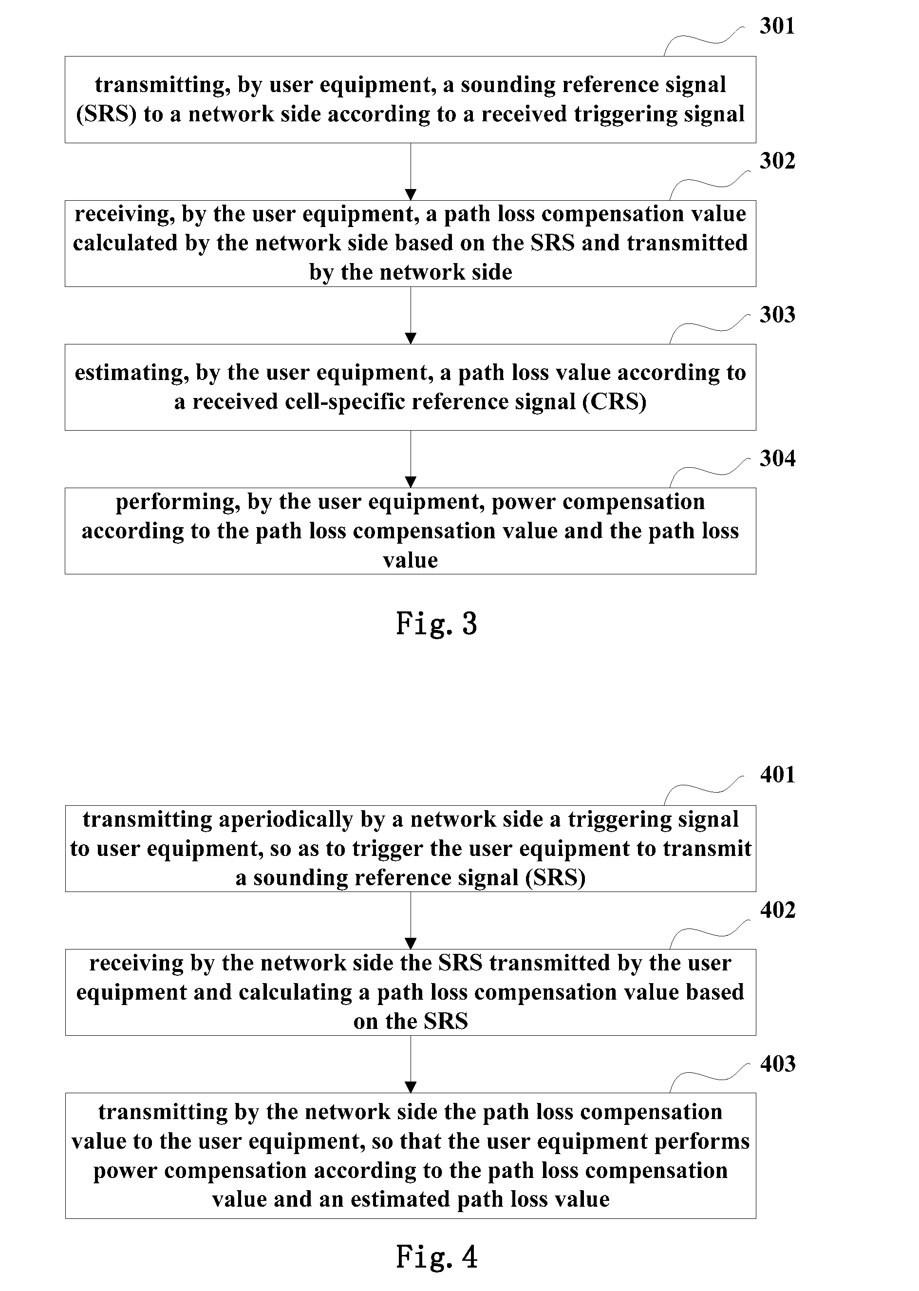
[0051]FIG. 4 is a flowchart of a method for uplink power control provided by an embodiment of the present invention, applicable to a network side in a heterogeneous deployment network scenario of CoMP transmission. Referring to FIG. 4, the method includes:

[0052]a triggering step 401: transmitting aperiodically by a network side a triggering signal to user equipment, so as to trigger the user equipment to transmit a sounding reference signal (SRS);

[0053]a processing step 402: receiving by the network side the SRS transmitted by the user equipment and calculating a path loss compensation value based on the SRS; and

[0054]a transmitting step 403: transmitting by the network side the path loss compensation value to the user equipment, so that the user equipment performs power compensation according to the path loss compensation value and an estimated path loss value.

[0055]In step 401, the eNB at the network side has a function of centralized control, which configures the UE with related ...

embodiment 3

[0064]FIG. 5 is a schematic diagram of the structure of UE provided by an embodiment of the present invention. Referring to FIG. 5, the UE includes:

[0065]a transmitting unit 51 configured to transmit a sounding reference signal (SRS) to a network side according to a received triggering signal;

[0066]a receiving unit 52 configured to receive a path loss compensation value calculated by the network side based on the SRS and transmitted by the network side;

[0067]an estimating unit 53 configured to estimate a path loss value according to a received cell-specific reference signal (CRS); and

[0068]a calculating unit 54 to perform power compensation according to the path loss compensation value and the path loss value.

[0069]In an embodiment, the estimating unit 53 includes:

[0070]a receiving module 531 configured to receive the cell-specific reference signals (CRS) transmitted by all the transmitting points of the network side; and

[0071]an estimating module 532 configured to estimate the path...


PUM


Abstract

A method and apparatus for uplink power control, including: transmitting, by user equipment, a sounding reference signal (SRS) to a network side according to a received triggering signal; receiving, by the user equipment, a path loss compensation value calculated based on the SRS and transmitted by the network side; estimating, by the user equipment, a path loss value according to a received cell-specific reference signal (CRS); and performing, by the user equipment, power compensation according to the path loss compensation and path loss values. On the basis of the original uplink power control performed according to the path loss estimated based on the downlink CRSs, the network side estimates the path loss compensation value of the UE by triggering the RRH UE to transmit aperiodic SRSs, and informs the UE in a semi-static manner, compensating for the inaccuracy of estimation of path loss and ensuring the efficiency of power control.

Description

CROSS-REFERENCE TO RELATED APPLICATIONS[0001]This is a continuation of International Application No. PCT / CN2011 / 078330, filed on Aug. 12, 2011, now pending, the contents of which are herein wholly incorporated by reference.TECHNICAL FIELD[0002]The present invention relates to the field of communications, and in particular to a method and apparatus for uplink power control in a heterogeneous deployment network.BACKGROUND ART[0003]In a long-term evolution-advanced (LTE-A) system, much attention is paid to an application scenario of coordinated multi-point (CoMP) transmission shown in FIG. 1. As shown in FIG. 1, such a scenario is a heterogeneous deployment network scenario, in which multiple low power remote radio heads (RRHs) coexist with an evolved Node B (eNB) in one cell with a same cell ID, the RRHs and the eNB being connected via optical fibers, and the eNB having a function of a centralized control.[0004]Among research points regarding the above scenario, one is an issue of upl...

Claims


Application Information

Patent Timeline
Patent Type & Authority Applications(United States)
IPC IPC(8): H04W52/14H04L5/00
CPCH04L5/0073H04W52/146H04L25/0224H04W52/242H04W52/244H04W52/325H04W52/40H04W52/04
Inventor XU, YUEQIAOZHANG, YIWANG, YIZHANG, YUANTAOZHOU, HUA
Owner FUJITSU LTD
Why Eureka
Try Eureka