Speed and Steering Control of a Hydraulically Driven Tractor

a hydraulically driven tractor and steering control technology, applied in the direction of vehicle mounted steering controls, non-deflectable wheel steering, agriculture tools and machines, etc., can solve the problems of limiting the transport speed of these windrowers, difficult to maintain commanded wheel speeds and importantly steering control, and synchronizing the fixed displacement motor speed of each individual hydrostatic system to permit a mechanical ratio change of gears. , the effect of eliminating deflections in linkages/isolators

Active Publication Date: 2014-05-22
MACDON INDS
View PDF10 Cites 18 Cited by
  • Summary
  • Abstract
  • Description
  • Claims
  • Application Information

AI Technical Summary

Benefits of technology

[0087]Thus, with each motor speed being independent within a range, this provides the ability to provide controllable steering deviation for auto-guidance applications where pump flow must remain fixed.
[0088]The arrangement described herein thus provides an arrangement to control differential automatic steering of the tractor without a valve, cylinders & linkage conventionally used to control pumps on

Problems solved by technology

There has been a limit to the transport speed of these windrowers due to instability at high speed with the drive wheels ahead of the castor wheels (cab forward).
The gearbox ratio is fixed as synchronizing a gearbox ratio shifting operation between two independent gearboxes would be difficult to maintain commanded wheel speeds and importantly steering control.
Synchronizing a fixed displacement motor speed of each individual hydrostatic system to permit a mechanical ratio change of gears would be equally complex and difficult.
A pair of infinitely variable ratio type gearboxes could be applied in place of or in series with a fixed gearbox, however it is easily realized this reduces the economy in application due to the complex nature of this type of mechanism.
In service brak

Method used


Image

  • Speed and Steering Control of a Hydraulically Driven Tractor
  • Speed and Steering Control of a Hydraulically Driven Tractor
  • Speed and Steering Control of a Hydraulically Driven Tractor

Examples


Embodiment Construction

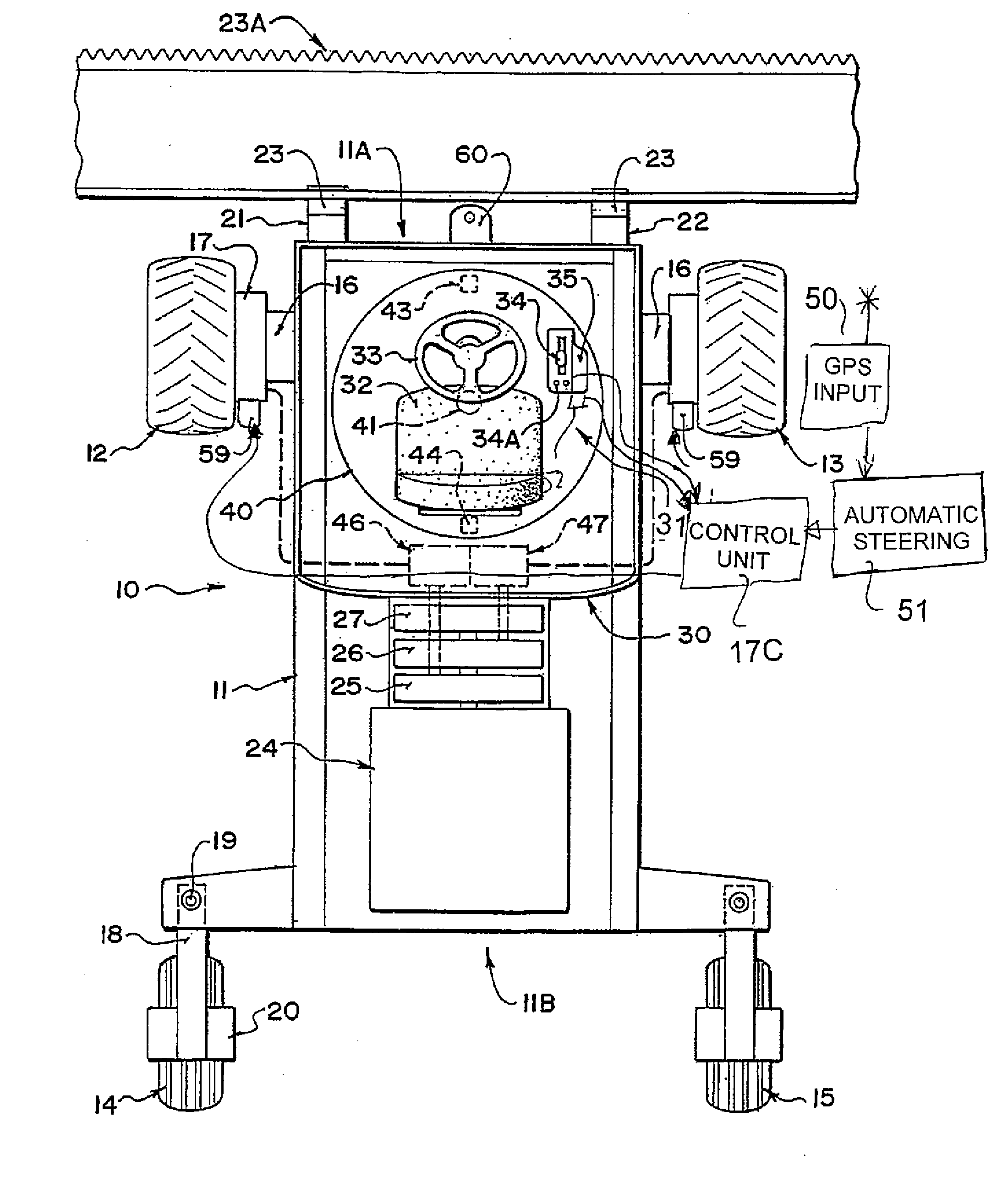
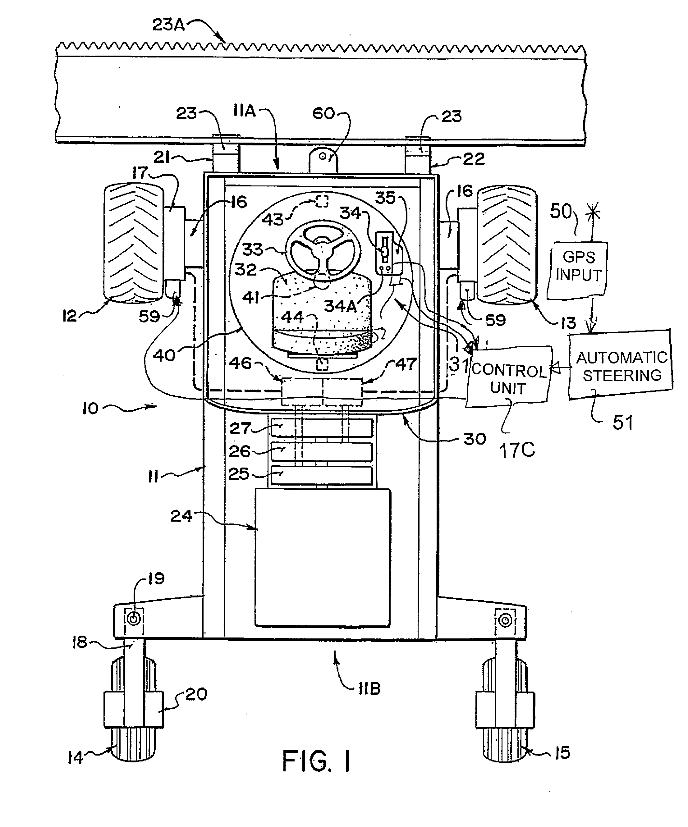
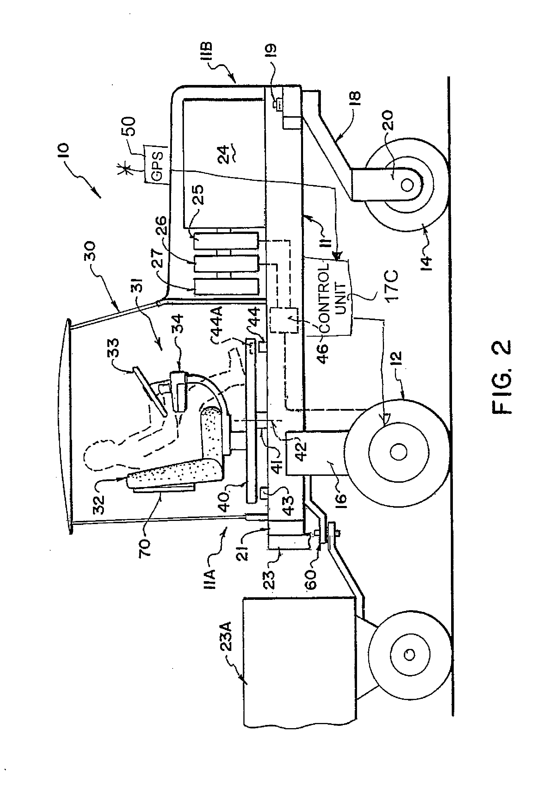
[0098]A swather tractor generally indicated at 10 includes a frame 11 which is carried on a first pair of driven ground wheels 12 and 13 and on a second pair of non-driven castor wheels 14 and 15. The driven wheels 12 and 13 are mounted on suitable supports 16 which support the ground wheels from the frame 11. The driven ground wheels 12 and 13 are each driven by a hydraulic motor 17 carried on the support 16 which receives hydraulic fluid under pressure from a supply line and drives the ground wheel at a rate of rotation dependant upon the rate of flow of the hydraulic fluid. The displacement of the motors 17 is adjustable by a servo 17A and 17B which act to cause step-less or continuous adjustment of the displacement over a range between a maximum position in which the wheel moves at minimum ground speed for a certain flow rate of the fluid and a minimum position in which the wheel moves at maximum ground speed for a certain flow rate of the fluid. The servos 17A and 17B are contr...


PUM


Abstract

A tractor has hydraulically driven wheels at a cab end and castor wheels at an engine end. Each driven wheels is driven by a hydraulic motor with a continuous adjustment of the motor displacement, with the motor being driven by a pump also having continuous displacement. The motor displacement is controlled by an electronic controller in response to stroking of the speed control lever to manage the displacement to provide required drive torques at different points in the stroke. There is provided an automatic steering system having a guidance controller arranged to receive GPS position information which controls the steering by differentially adjusting the displacement of the motors so that the automatic steering is independent of the manual steering which controls the pumps.

Description

[0001]This invention relates to a hydraulically driven tractor of the type, commonly but not necessarily used as a swather tractor, which is supported on a pair of hydraulically driven wheels and a pair of castor wheels and steered by a differential speed between the driven wheels.RELATED PRIOR PATENTS[0002]Reference is made to the following patents and applications by the same assignee, the disclosure of each of which is incorporated herein by reference as they disclose further details which may be used in the machines disclosed herein:[0003]U.S. Pat. No. 8,245,489 (Talbot) issued Aug. 21, 2012 which discloses a combine harvester where the header is carried on gauge wheels.[0004]U.S. Pat. No. 8,225,903 (Dunn) issued Jul. 24 200712 which discloses a tractor of the type suitable for use herein where the tractor includes a suspension system.[0005]U.S. Pat. No. 8,020,648 (Otto) issued Sep. 20, 2011 which discloses a tractor of the type suitable for use herein where the tractor has a re...

Claims


Application Information

Patent Timeline
IPC IPC(8): B62D11/04
CPCB62D11/04B62D11/001A01B69/007B62D1/22
Inventor OTTO, PHILMACGREGOR, DONBERGMAN, LEONARD
Owner MACDON INDS
Why Eureka
Try Eureka