Hydrokinetic Energy Conversion System with Buoyancy and Ballast Controls to Harness Underwater Currents for the Generation of Electrical Power

a technology of hydrokinetic energy and underwater current, which is applied in the direction of electrical generator control, machines/engines, mechanical equipment, etc., can solve the problems of underwater current flow and the inability to utilize slow moving currents

Active Publication Date: 2014-05-22
HYDRO ALTERNATIVE ENERGY
View PDF6 Cites 22 Cited by
  • Summary
  • Abstract
  • Description
  • Claims
  • Application Information

AI Technical Summary

Benefits of technology

[0016]In another embodiment, the ballast control tanks are disposed or hung on or about the outboard sides of the radial shrouds. These ballast pods include ballast controls, passive and hard ballast tanks and sources of compressed air for soft ballast control volumes for the system.

Problems solved by technology

However, there is a deficiency in utilization of slow moving, underwater current flows, particularly underwater ocean currents.
While these high water velocities offer the potential for the extraction of large amounts of hydrokinetic energy, these velocities are present in a very small percentage of the world's ocean waters.

Method used


Image

  • Hydrokinetic Energy Conversion System with Buoyancy and Ballast Controls to Harness Underwater Currents for the Generation of Electrical Power
  • Hydrokinetic Energy Conversion System with Buoyancy and Ballast Controls to Harness Underwater Currents for the Generation of Electrical Power
  • Hydrokinetic Energy Conversion System with Buoyancy and Ballast Controls to Harness Underwater Currents for the Generation of Electrical Power

Examples


Embodiment Construction

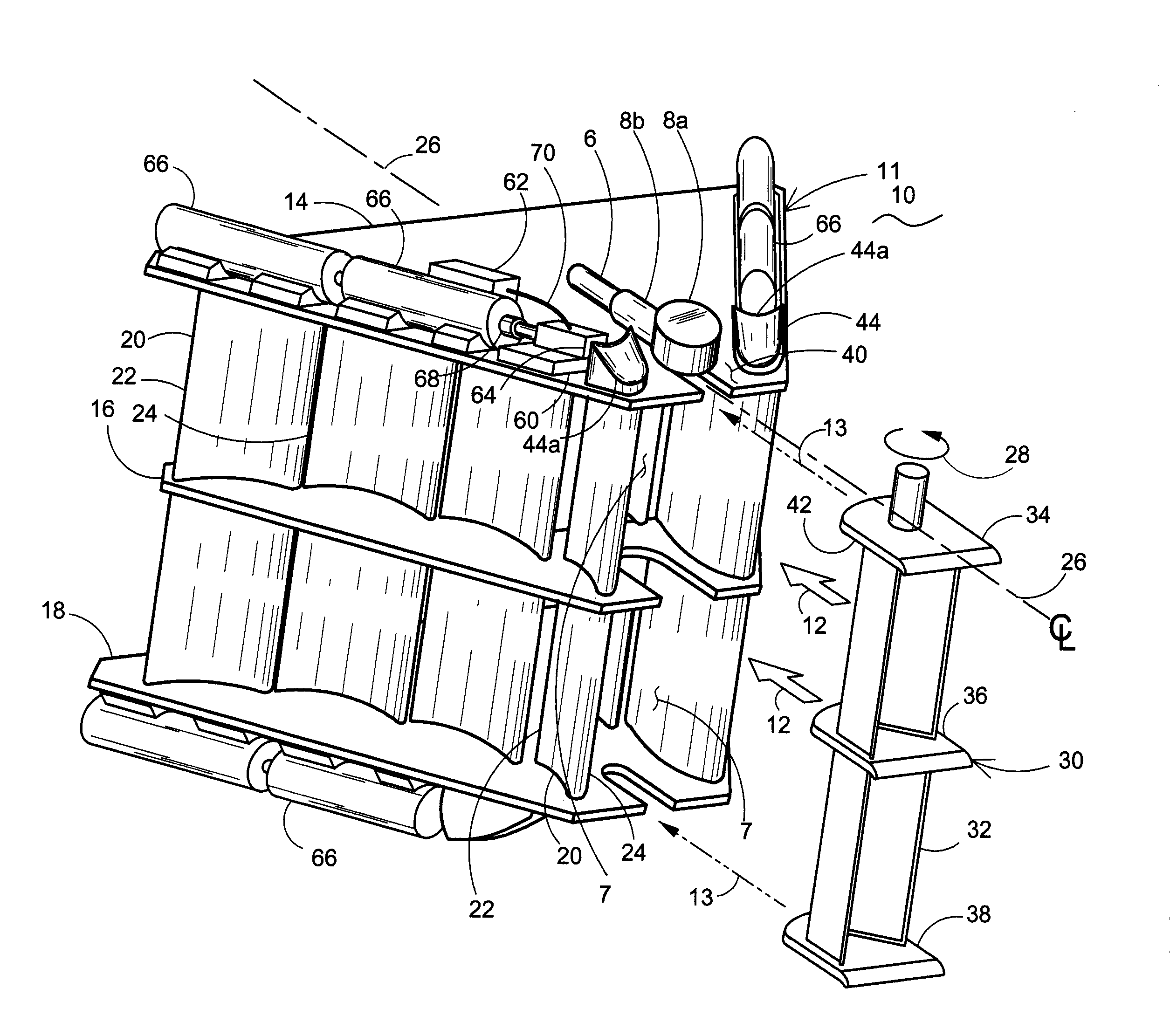
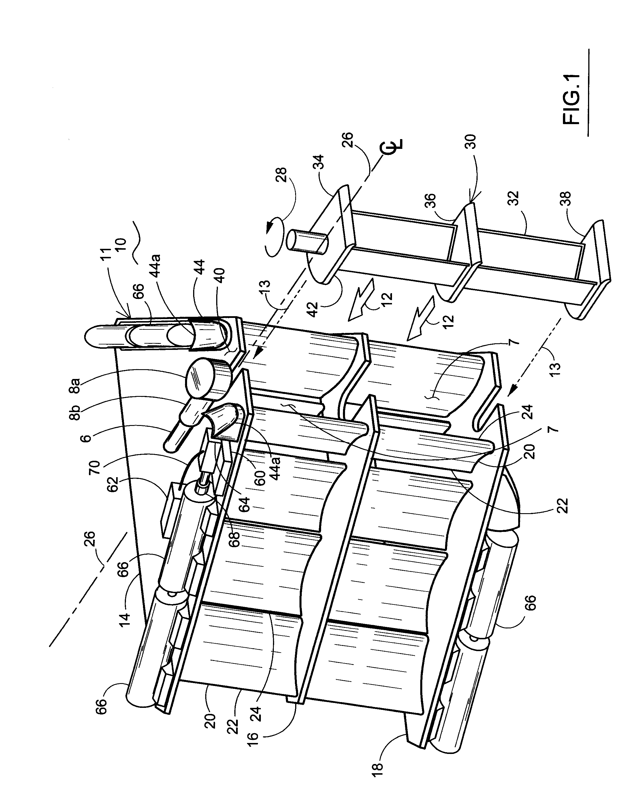
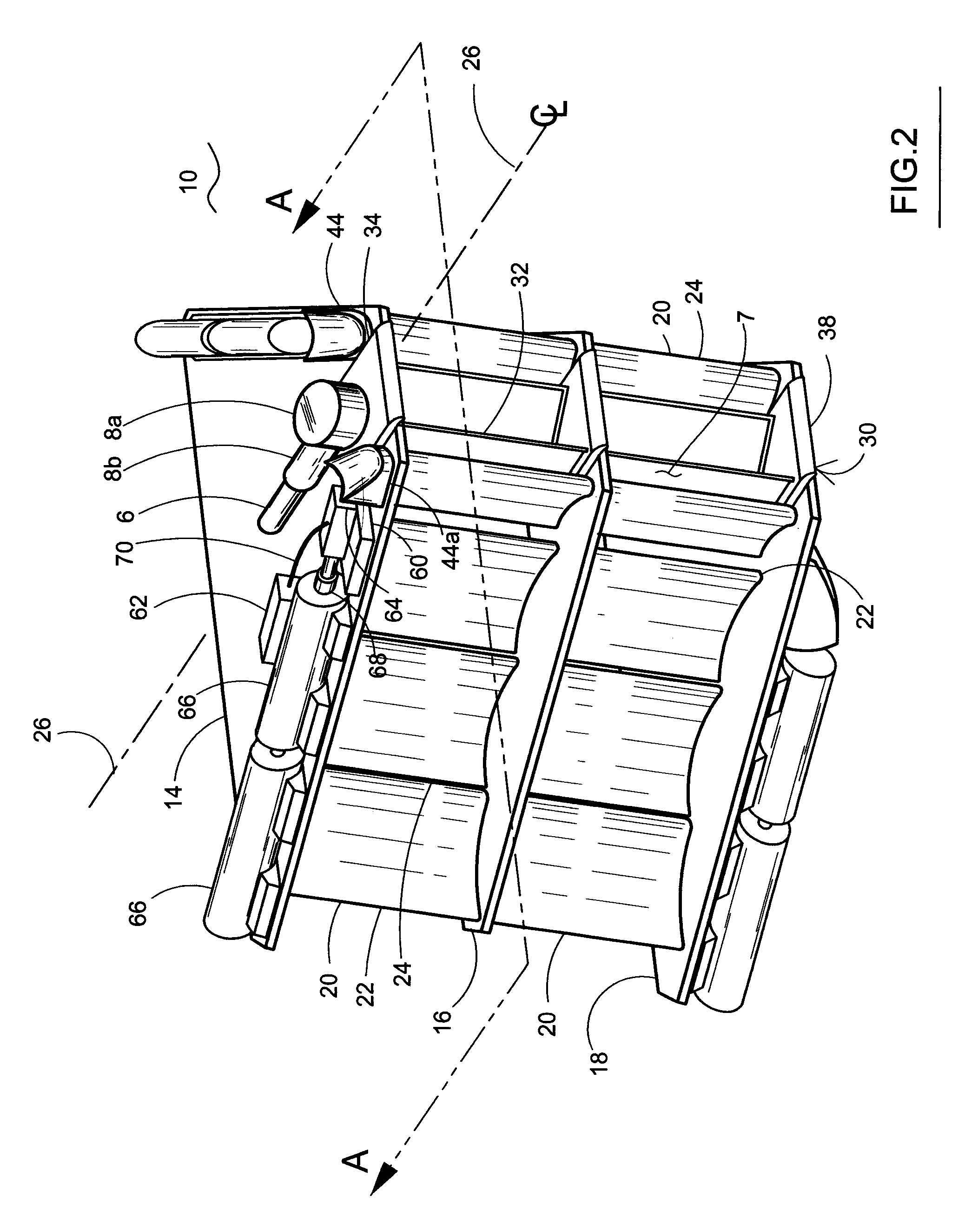
[0038]The present invention relates to a hydrokinetic energy conversion system with buoyancy and ballast controls which harness underwater current for the generation of electrical power. FIGS. 1-5 generally illustrate a laminar flow shroud used in connection with a perpendicular panel turbine. FIGS. 6-6B generally show a radial flow shroud with an inline or axial turbine. FIGS. 7 and 8 diagrammatically illustrate some mooring systems. It should be noted that although a laminar flow hydrofoil is shown in FIGS. 7 and 8, the hydrofoils in the radial flow conversion system may include the same features. FIG. 9 diagrammatically illustrates a process control system for the ballast and buoyancy control.

[0039]Further, it should be noted that the concepts regarding hydrofoil construction in FIGS. 3A, 3B, 4, 4A and 5 can be applied equally to the radial flow shroud hydrofoils which are diagrammatically illustrated in FIG. 6A. For example, the radial flow shroud foil 6 in FIG. 6A may include i...


PUM


Abstract

The hydrokinetic energy conversion system uses, in one embodiment, a perpendicular turbine coupled to an electrical generator and a laminar water flow shroud. The ballast and buoyancy system includes hydrofoils defining lateral sides of the shroud mounted on upper and lower decks. Ballast chambers are defined in some or all of the foils and each has a gas intake port and a water ballast output port. The shroud carries a source of compressed air, valves for control of air flow into the ballast chambers. The ballast and buoyancy system includes a control system with sensors for depth, pitch, yaw and roll of the shroud which generates valve control commands. Another embodiment utilizes an inline turbine and a radial water flow shroud with a plurality of circumferential hydrofoils. Struts mount the turbine near the primary hydrofoil and braces attach ring hydrofoils together. Alternatively, ballast chambers are defined in outboard-mounted ballast pods.

Description

[0001]The present invention relates to a system which converts hydrokinetic underwater current flow into electrical power.BACKGROUND OF THE INVENTION[0002]Prior art systems utilize flowing water from dams, called hydroelectric plants, to generate electrical power. Additionally, turbines have been used to convert wind or airflow into electrical power. However, there is a deficiency in utilization of slow moving, underwater current flows, particularly underwater ocean currents.[0003]Velocity is a factor in the amount of hydrokinetic energy that can be extracted from flowing water. Several prior art hydrokinetic electrical generators work in very high velocity or flow environments, such as in the range of 3, 4 or 5 meters per second (about 6, 8 or 10 knots). While these high water velocities offer the potential for the extraction of large amounts of hydrokinetic energy, these velocities are present in a very small percentage of the world's ocean waters.[0004]Flow velocity is only one f...

Claims


Application Information

Patent Timeline
Patent Type & Authority Applications(United States)
IPC IPC(8): F03B1/00
CPCF03B1/00F03B17/061F03B17/065F05B2240/13F05B2240/97F05B2270/18Y02E10/30F03B17/062Y02E10/20
Inventor ANTONUCCI, MARKLEBER, MARK A.HAAS, JOEL C.DUPONT, DAVID L.
Owner HYDRO ALTERNATIVE ENERGY
Why Eureka
Try Eureka