Methods and Scatterometers, Lithographic Systems, and Lithographic Processing Cells

a scatterometer and lithographic technology, applied in the field of methods and scatterometers, can solve the problems of perturbing metrology, metrology problems, undesirable loading and process effects at (sub-)micrometer scal

Active Publication Date: 2014-05-22
ASML NETHERLANDS BV
View PDF21 Cites 40 Cited by
  • Summary
  • Abstract
  • Description
  • Claims
  • Application Information

AI Technical Summary

Problems solved by technology

These micro-loading and process effects at (sub-)micrometer scale are undesirable for the production of semiconductor devices, and may perturb metrology on small targets differently than product features or differently over the width of the target.
Particularly non-uniformity at the target-edge can cause metrology problems for overfill illumination, where the detection beam is larger than the target, combined with pupil-detection in optical metrology.
Micro-loading and process effects on metrology targets are difficult to detect because it concerns properties that occur within the processed layers of a wafer, for example the local etch rate for the bottom-grating of an overlay diffraction grating.
However, these techniques have a limited sensitivity with respect to profile asymmetries of measured structures.
Specific disadvantages of optical microscopy and top-down SEM are:
iv. they cannot be used to improve the measurement of the actual target, they can only help for deciding if a metrology target can be used or not for a measurement.
However, both are time-consuming, destructive techniques because the wafer has to be cut along a line at the structure of interest for the cross-sectional view.
Furthermore, only a single local cross-section can be prepared; TEM and cross-section SEM do not allow for extraction of 2-dimensional information locally over the wafer field.
However the technique is rather slow and it interrupts the production of wafers.
However, diffraction-based pupil detection combined with reconstruction is only able to probe process-effects on a large scale of the order of the illumination spot size (tens of microns).
For pupil detection, the local information at sub-micron scale is hardly accessible (unless entire targets or structures are completely reconstructed, using for example an electro-magnetic solver in a recurrent solving loop, however that requires an unfeasible number of fit parameters describing e.g., the side-wall-angle of each individual line in the grating structure).
Furthermore, the reconstruction necessary to retrieve the inspection information is time-expensive.

Method used


Image

  • Methods and Scatterometers, Lithographic Systems, and Lithographic Processing Cells
  • Methods and Scatterometers, Lithographic Systems, and Lithographic Processing Cells
  • Methods and Scatterometers, Lithographic Systems, and Lithographic Processing Cells

Examples


Embodiment Construction

[0051]This specification discloses one or more embodiments that incorporate the features of this invention. The disclosed embodiment(s) merely exemplify the present invention. The scope of the present invention is not limited to the disclosed embodiment(s). The present invention is defined by the claims appended hereto.

[0052]The embodiment(s) described, and references in the specification to “one embodiment”, “an embodiment”, “an example embodiment”, etc., indicate that the embodiment(s) described may include a particular feature, structure, or characteristic, but every embodiment may not necessarily include the particular feature, structure, or characteristic. Moreover, such phrases are not necessarily referring to the same embodiment. Further, when a particular feature, structure, or characteristic is described in connection with an embodiment, it is understood that it is within the knowledge of one skilled in the art to effect such feature, structure, or characteristic in connect...


PUM

PropertyMeasurementUnit
wavelengthaaaaaaaaaa
sizeaaaaaaaaaa

Abstract

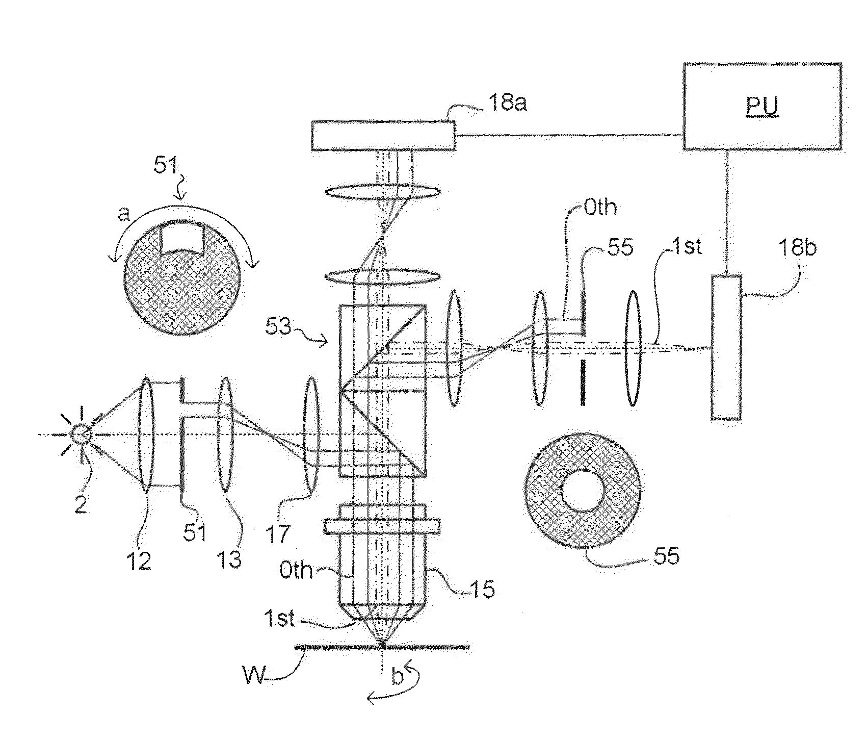
In a method of determining the focus of a lithographic apparatus used in a lithographic process on a substrate, the lithographic process is used to form a structure on the substrate, the structure having at least one feature which has an asymmetry in the printed profile which varies as a function of the focus of the lithographic apparatus on the substrate. A first image of the periodic structure is formed and detected while illuminating the structure with a first beam of radiation. The first image is formed using a first part of non-zero order diffracted radiation. A second image of the periodic structure is formed and detected while illuminating the structure with a second beam of radiation. The second image is formed using a second part of the non-zero order diffracted radiation which is symmetrically opposite to the first part in a diffraction spectrum. The ratio of the intensities of the measured first and second portions of the spectra is determined and used to determine the asymmetry in the profile of the periodic structure and / or to provide an indication of the focus on the substrate. In the same instrument, an intensity variation across the detected portion is determined as a measure of process-induced variation across the structure. A region of the structure with unwanted process variation can be identified and excluded from a measurement of the structure.

Description

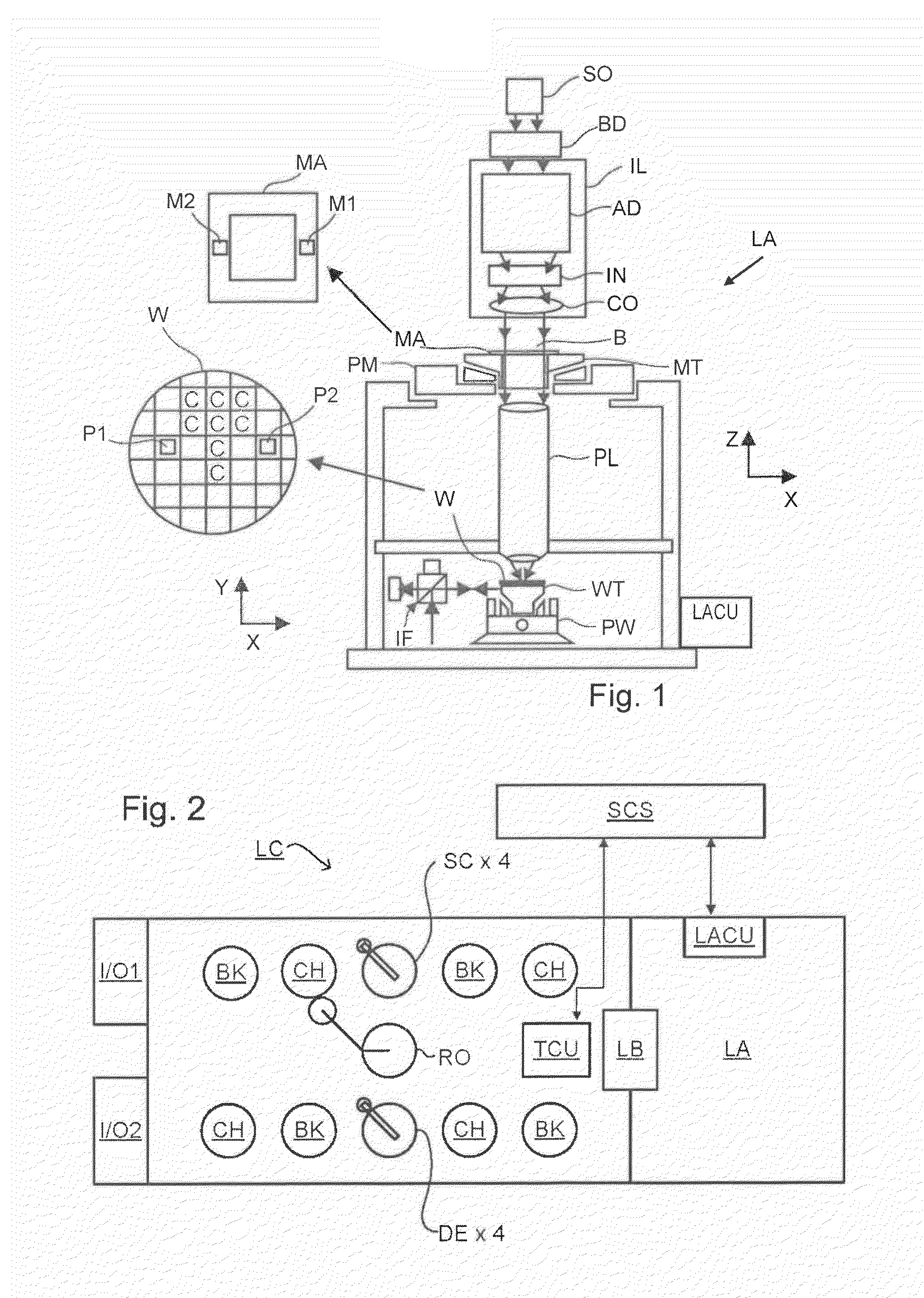
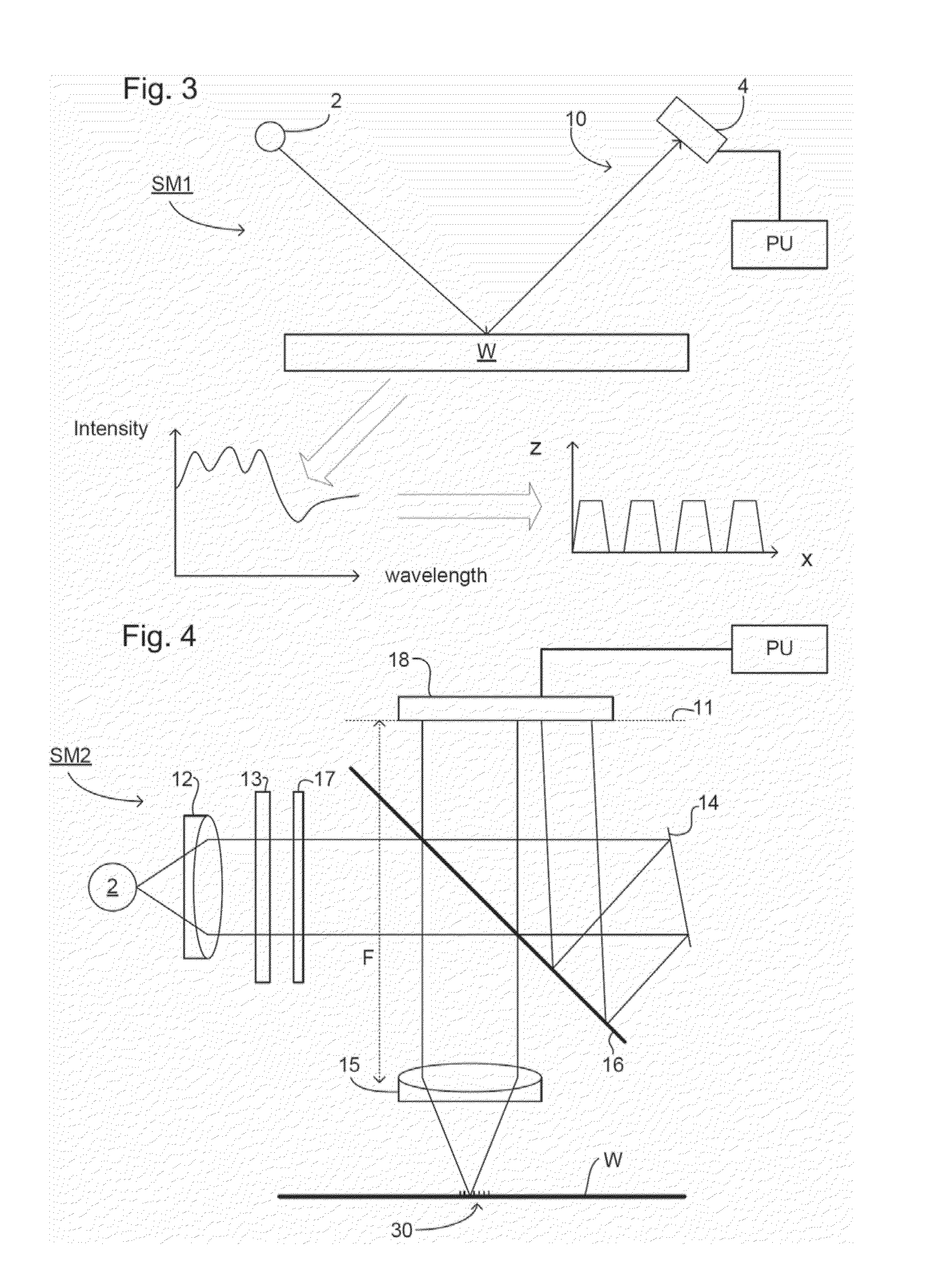
[0001]This patent application is related to U.S. application Ser. No. 12 / 846,652 and U.S. Provisional Patent Application No. 61 / 230,331, which are incorporated by reference herein in their entiretiesBACKGROUND[0002]1. Field of the Invention[0003]The present invention relates to methods and scatterometers usable, for example, in the manufacture of devices by lithographic techniques.[0004]2. Background Art[0005]A lithographic apparatus is a machine that applies a desired pattern onto a substrate, usually onto a target portion of the substrate. A lithographic apparatus can be used, for example, in the manufacture of integrated circuits (ICs). In that instance, a patterning device, which is alternatively referred to as a mask or a reticle, may be used to generate a circuit pattern to be formed on an individual layer of the IC. This pattern can be transferred onto a target portion (e.g., comprising part of, one, or several dies) on a substrate (e.g., a silicon wafer). Transfer of the pat...

Claims


Application Information

Patent Timeline
Patent Type & Authority Applications(United States)
IPC IPC(8): G03F7/20G01N21/88
CPCG01N21/88G03F7/70191G03F7/70641G01B11/24G01B11/30G01N21/47H01L21/0274G03F7/70625G03F7/70633G03F7/7065G03F7/70608G01B11/02G01B11/22
Inventor CRAMER, HUGO AUGUSTINUS JOSEPHDEN BOEF, ARIE JEFFREYMEGENS, HENRICUS JOHANNE LAMBERTUSSMILDE, HENDRIK JAN HIDDESCHELLEKENS, ADRIANUS JOHANNE HENDRIKUSKUBIS, MICHAEL
Owner ASML NETHERLANDS BV
Why Eureka
Try Eureka