Spectroscopic scatterometer system

a scatterometer and spectroscopic technology, applied in the field of scatterometers, can solve the problems of increasing exponentially the number of signatures that have to be calculated, the scatterometer that measures the entire diffraction envelope does not provide the data required for an accurate analysis, and the process steps of state-of-the-art devices

Inactive Publication Date: 2007-02-06
KLA TENCOR TECH CORP
View PDF72 Cites 26 Cited by
  • Summary
  • Abstract
  • Description
  • Claims
  • Application Information

AI Technical Summary

Benefits of technology

[0018]One aspect of the invention is directed towards a method of measuring one or more parameters of a diffracting structure on an underlying structure, said underlying structure having a film thickness and an optical index, comprising providing an optical index and a film thickness of the underlying structure; constructing a reference database of one or more parameters related to said diffracting structure using said optical index and film thickness of the underlying structure; and directing a beam of electromagnetic radiation at a plurality of wavelengths at said diffracting structure. The method further comprises detecting intensities or ellipsometric parameters at said plurality of wavelengths of a diffraction from said structure; and comparing said detected intensities or ellipsometric parameters to said database to determine said one or more parameters.

Problems solved by technology

The state-of-the-art devices require a considerable number of process steps.
A traditional scatterometer that measures the entire diffraction envelope does not provide the data required for an accurate analysis.
This is undesirable since frequently, these quantities are not known in advance.
By thus increasing the number of variables in the model, the number of signatures that has to be calculated increase exponentially, so that the computation time involved renders such approach inappropriate for real-time measurements.
Furthermore, since the intensity of the particular diffraction order as a function of incidence angle of the sampling beam is acquired sequentially as the incident angle is varied, data acquisition for the 2-Θ plot or scatter “signature” is slow and the detected intensity is subject to various noise sources such as system vibration and random electronic noise which may change over time as the incident angle is varied.
Ziger's approach is limited and impractical, since it requires replication of multiple reference patterns analogous to the target pattern and measurements of such reference patterns to construct a database before a measurement can be made of the target pattern.
In other words, Ziger's method cannot be used to measure the grating characteristics on line patterns made of a material having a reflectivity similar to that of the underlying substrate.
None of the above-described approaches is entirely satisfactory.

Method used


Image

  • Spectroscopic scatterometer system
  • Spectroscopic scatterometer system
  • Spectroscopic scatterometer system

Examples


Embodiment Construction

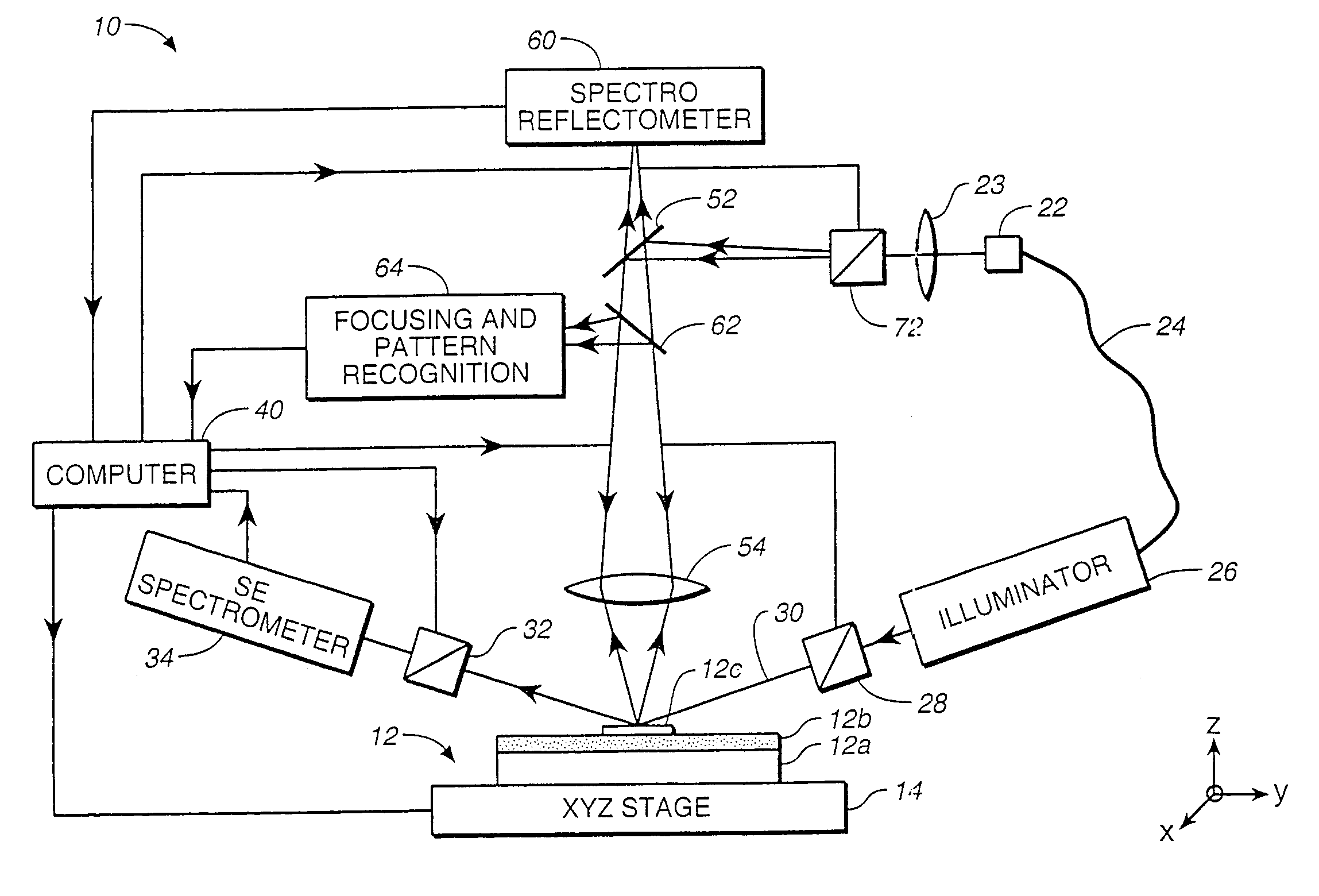
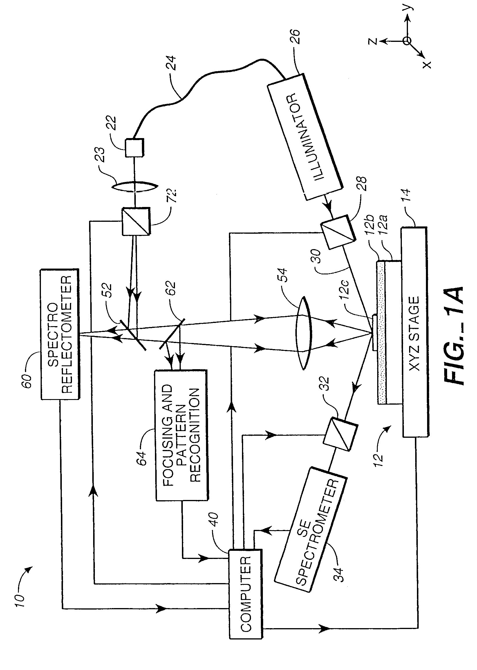
[0035]This invention is based on the recognition that, by measuring or otherwise obtaining characteristics such as the film thickness and optical index of the underlying films underneath the diffracting structure, the subsequent tasks of construction of a database and matching a signature of the diffracting structure to the database are much simplified. Furthermore, if spectroscopic ellipsometry is used to measure the film thickness and optical index of the underlying film(s) under the diffracting structure, an instrument which can be used for spectroscopic ellipsometry as well as for spectroscopic scatterometry may be provided for carrying out both functions. In the preferred embodiment, the spectroscopic ellipsometer and its associated spectroscopic scatterometer in the instrument may share many common optical elements to reduce the cost of the combined instrument and simplify its operation.

[0036]By first measuring the film thickness and optical refractive index of the underlying ...


PUM

PropertyMeasurementUnit
wavelengthsaaaaaaaaaa
oblique angleaaaaaaaaaa

Abstract

Before the diffraction from a diffracting structure on a semiconductor wafer is measured, where necessary, the film thickness and index of refraction of the films underneath the structure are first measured using spectroscopic reflectometry or spectroscopic ellipsometry. A rigorous model is then used to calculate intensity or ellipsometric signatures of the diffracting structure. The diffracting structure is then measured using a spectroscopic scatterometer using polarized and broadband radiation to obtain an intensity or ellipsometric signature of the diffracting structure. Such signature is then matched with the signatures in the database to determine the grating shape parameters of the structure.

Description

CROSS REFERENCE TO RELATED APPLICATION [0001]This application is a continuation of U.S. patent application Ser. No. 09 / 036,557, filed Mar. 6, 1998, now U.S. Pat. No. 6,483,580.BACKGROUND OF THE INVENTION[0002]This invention relates in general to scatterometers and in particular, to a spectroscopic scatterometer system.[0003]As the integration and speed of microelectronic devices increase, circuit structures continue to shrink in dimension size and to improve in terms of profile edge sharpness. The state-of-the-art devices require a considerable number of process steps. It is becoming increasingly important to have an accurate measurement of submicron linewidth and quantitative description of the profile of the etched structures on a pattern wafer at each process step. Furthermore, there is a growing need for wafer process monitoring and close-loop control such as focus-exposure control in photolithography.[0004]Diffraction-based analysis techniques such as scatterometry are especial...

Claims


Application Information

Patent Timeline
Patent Type & Authority Patents(United States)
IPC IPC(8): G01J4/00G01B11/02G01B11/06G01N21/21G01N21/27G01N21/95G01N21/956G03F7/20H01L21/66
CPCG01B11/0641G01N21/211G01N21/4788G01N21/55G01N21/9501G01N21/956G01N21/95607G03F7/70491G03F7/70616G03F7/70625H01L2924/0002G01N2021/213G01N2021/556G01N2021/95615H01L22/12H01L2924/00
Inventor XU, YIPINGABDULHALIM, IBRAHIM
Owner KLA TENCOR TECH CORP
Why Eureka
Try Eureka