Method and Apparatus for Controlling a Lithographic Apparatus

a technology of lithographic apparatus and control method, which is applied in the direction of photomechanical treatment, printers, instruments, etc., can solve the problems of ineffective maintenance, inability to achieve optimal correction, and need to perform more frequent, so as to improve off-line parameterization modeling

Active Publication Date: 2011-08-25
ASML NETHERLANDS BV
View PDF17 Cites 27 Cited by
  • Summary
  • Abstract
  • Description
  • Claims
  • Application Information

AI Technical Summary

Benefits of technology

[0010]Therefore, what is needed is an effective system a

Problems solved by technology

This can lead to ineffective maintenance by applying non-optimum corrections at the lithographic apparatus.
Inaccuracy of this maintenance results in the need to perform more frequent on-line re-calibration of the lithographic apparatus or leads to specific corrections for field positions and size of the calibration that are not generic for other field p

Method used


Image

  • Method and Apparatus for Controlling a Lithographic Apparatus
  • Method and Apparatus for Controlling a Lithographic Apparatus
  • Method and Apparatus for Controlling a Lithographic Apparatus

Examples


Embodiment Construction

[0027]This specification discloses one or more embodiments that incorporate the features of this invention. The disclosed embodiment(s) merely exemplify the invention. The scope of the invention is not limited to the disclosed embodiment(s). The invention is defined by the claims appended hereto.

[0028]The embodiment(s) described, and references in the specification to “one embodiment,”“an embodiment,”“an example embodiment,” etc., indicate that the embodiment(s) described may include a particular feature, structure, or characteristic, but every embodiment may not necessarily include the particular feature, structure, or characteristic. Moreover, such phrases are not necessarily referring to the same embodiment. Further, when a particular feature, structure, or characteristic is described in connection with an embodiment, it is understood that it is within the knowledge of one skilled in the art to affect such feature, structure, or characteristic in connection with other embodiments...


PUM


Abstract

A lithographic exposure process is performed on a substrate using a scanner. The scanner comprises several subsystems. There are errors in the overlay arising from the subsystems during the exposure. The overlay errors are measured using a scatterometer to obtain overlay measurements. Modeling is performed to separately determine from the overlay measurements different subsets of estimated model parameters, for example field distortion model parameters, scan/step direction model parameters and position/deformation model parameters. Each subset is related to overlay errors arising from a corresponding specific subsystem of the lithographic apparatus. Finally, the exposure is controlled in the scanner by controlling a specific subsystem of the scanner using its corresponding subset of estimated model parameters. This results in a product wafer being exposed with a well controlled overlay.

Description

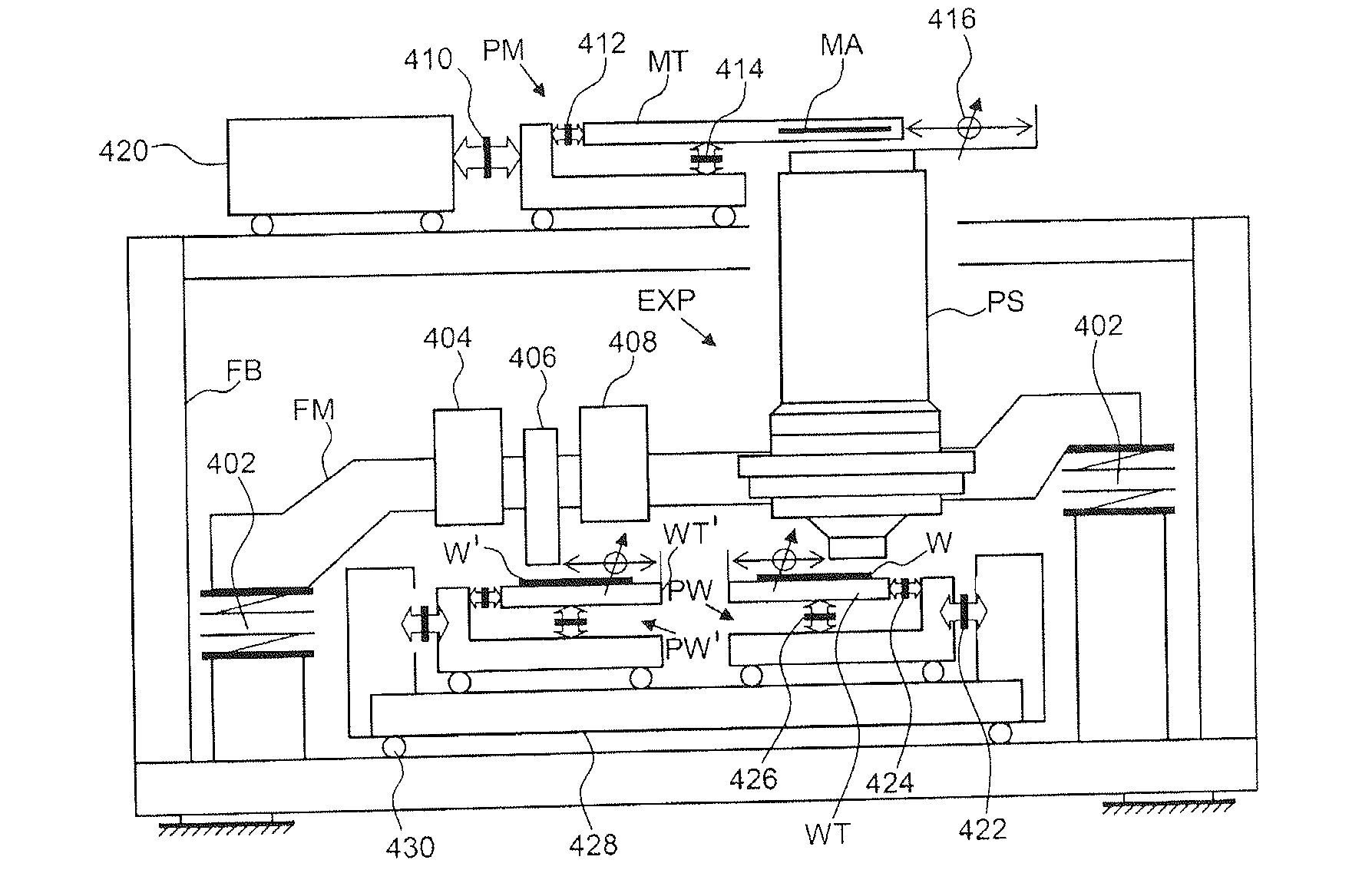
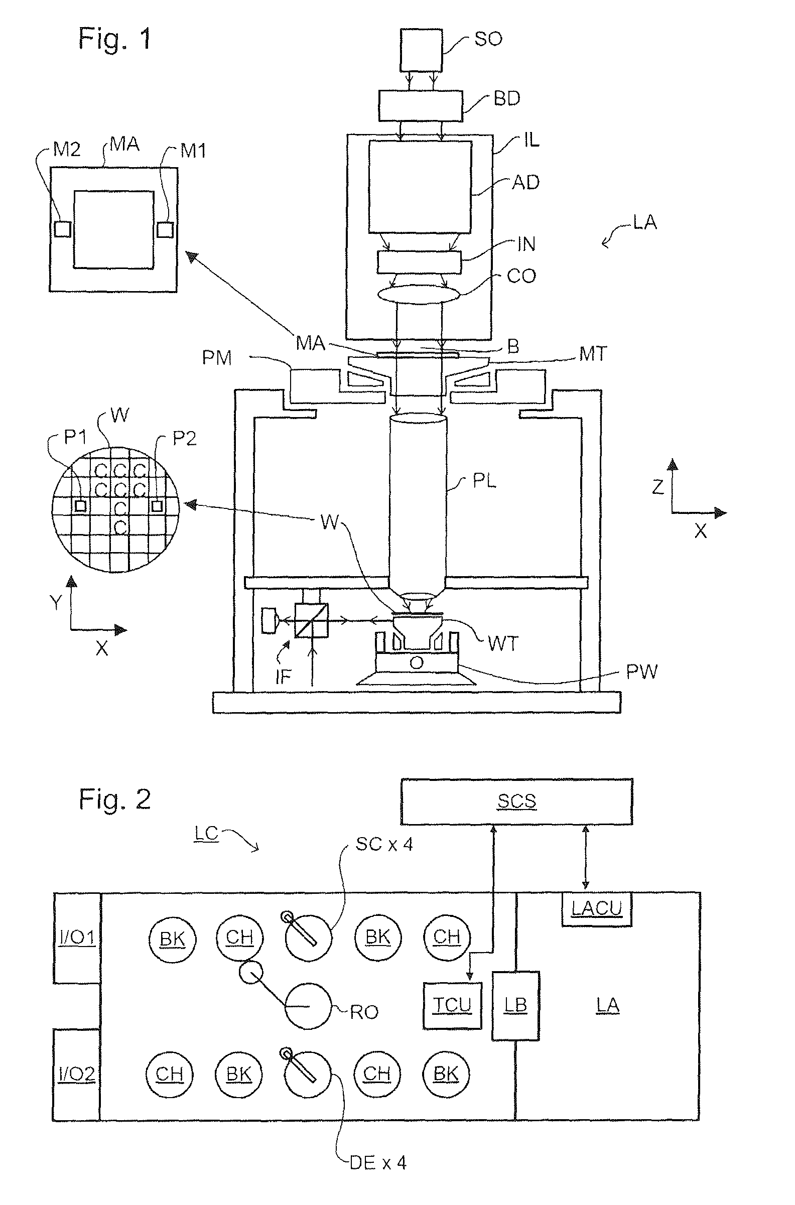
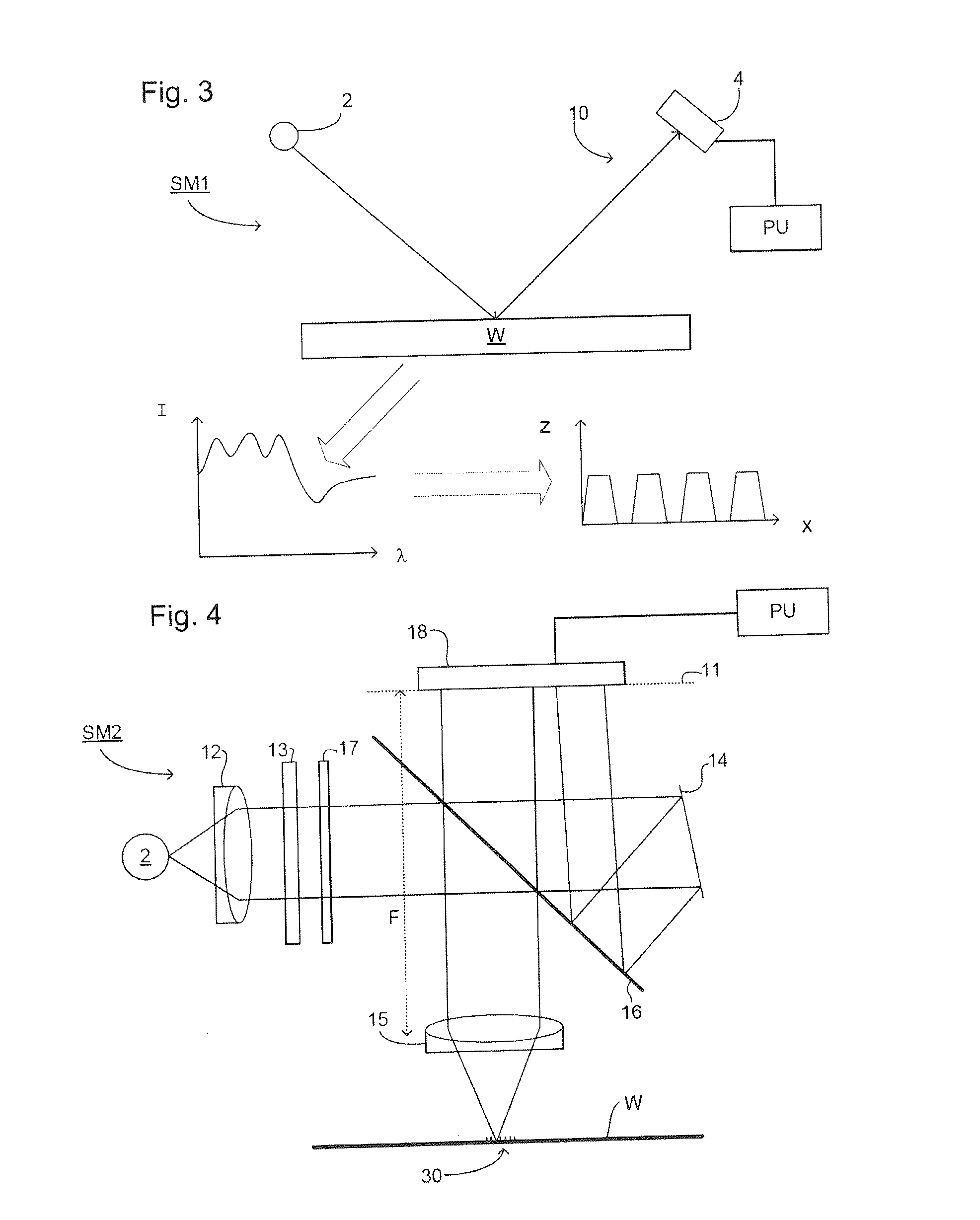
CROSS REFERENCE TO RELATED APPLICATIONS[0001]This claims benefit under 35 U.S.C. 119(e) to U.S. Provisional Patent Application No. 61 / 306,111, filed Feb. 19, 2010, which is incorporated by reference herein in its entirety.BACKGROUND[0002]1. Field of the Invention[0003]The present invention relates to controlling lithographic apparatus for correcting errors, such as overlay, in the lithographic process usable, for example, in the manufacture of devices by lithographic techniques.[0004]2. Related Art[0005]A lithographic apparatus is a machine that applies a desired pattern onto a substrate, usually onto a target portion of the substrate. A lithographic apparatus can be used, for example, in the manufacture of integrated circuits (ICs). In that instance, a patterning device, which is alternatively referred to as a mask or a reticle, may be used to generate a circuit pattern to be formed on an individual layer of the IC. This pattern can be transferred onto a target portion (e.g., compr...

Claims


Application Information

Patent Timeline
IPC IPC(8): G03B27/42
CPCG03F7/705G03F7/70633G03F7/70525G03F7/70516G03F7/70483H01L21/0274
Inventor MENCHTCHIKOV, BORISPADIY, ALEXANDER VIKTOROVYCH
Owner ASML NETHERLANDS BV
Why Eureka
Try Eureka