Holographic scatterometer for detection and analysis of wafer surface deposits

a holographic scatterometer and wafer surface technology, applied in the field of optical inspection instruments, can solve the problems of inability to perform in-process surface inspection, and insufficient resolution and accuracy of optical microscopes in general

Inactive Publication Date: 2002-10-31
SENTEC CORP
View PDF0 Cites 24 Cited by
  • Summary
  • Abstract
  • Description
  • Claims
  • Application Information

AI Technical Summary

Problems solved by technology

For sub-micron resolution, most of these techniques are not suitable for in-process surface inspection.
High-resolution microscopes require cumbersome surface preparations and expensive operations.
Optical microscopes, in general, do not have sufficient resolution and accuracy.
Ellipsometry or spectroscopy also do not provide adequate surface roughness information.
The problems with this method are: (a) a critical focusing requirement, (b) low throughput rate due to slow scanning, (c) inadequate lateral resolution (>0.2 mm), (d) limited sensitivity (<100 nm), and (e) inadequate information on the surface deposit materials.
In particular with regard to problem (b), a serious drawback with microscopy, in general, is in assessing the number of defects over a large wafer area by scanning with a micron-sized area of view.
Another candidate technology, namely scatterometry, has a drawback as presently, generally implemented.
A significant limitation with scatterometry is that the intensity of scattering is typically measured at oblique angles, excluding the specular beam.
The Batchelder and Tsuji heterodyne interferometers provide photon counting detection (Shot noise limited) for the small scattered light from the particles, although the grazing illumination described in both patents will only provide lower sensitivity (only good for a larger particle detection).
The problem with these methods is that they cannot effectively discriminate particles on the wafer surface, (which are desired to be detected) from particles within the beam suspended in the air, (which are not desired to be detected.)
This will increase a chance of producing a false signal.
However, this imaging method does not provide photon-counting detection.
Also, the rescanning of the surface is time consuming a particularly undesirable for commercial applications.
Small particles on an unpatterned wafer surface are often undesirable and must be detected for remedial action.
This approach may shorten the calculation time when the waveform r(x, y) is complex.
Note that the basic signal-to-noise of the system is limited by the optical power that one can use.
It is well known that the noise level of CCDs is greater than that of silicon photo-detectors.

Method used


Image

  • Holographic scatterometer for detection and analysis of wafer surface deposits
  • Holographic scatterometer for detection and analysis of wafer surface deposits
  • Holographic scatterometer for detection and analysis of wafer surface deposits

Examples


Embodiment Construction

[0084] Let A equal the intensity of a single pixel corresponding to a phase difference between the signal beam S and the reference beam R, namely, .theta.; B equal to the intensity of another pixel (in the same line) corresponding to .theta.+90.degree.; C equal to the intensity of yet another pixel (in the same line) corresponding to .theta.+180.degree.; and D equal to the intensity of still another pixel (in the same line) corresponding to .theta.+270.degree.. Evaluating equation (9) yields:

Ipro(m)=[(A-C).sup.2-(B-D).sup.2].sup.1 / 2

[0085] In the TDI mode of operation, a "constellation" of 4 points gets brighter and brighter when a particle P is present on surface 12. Two phases may also be used rather than four.

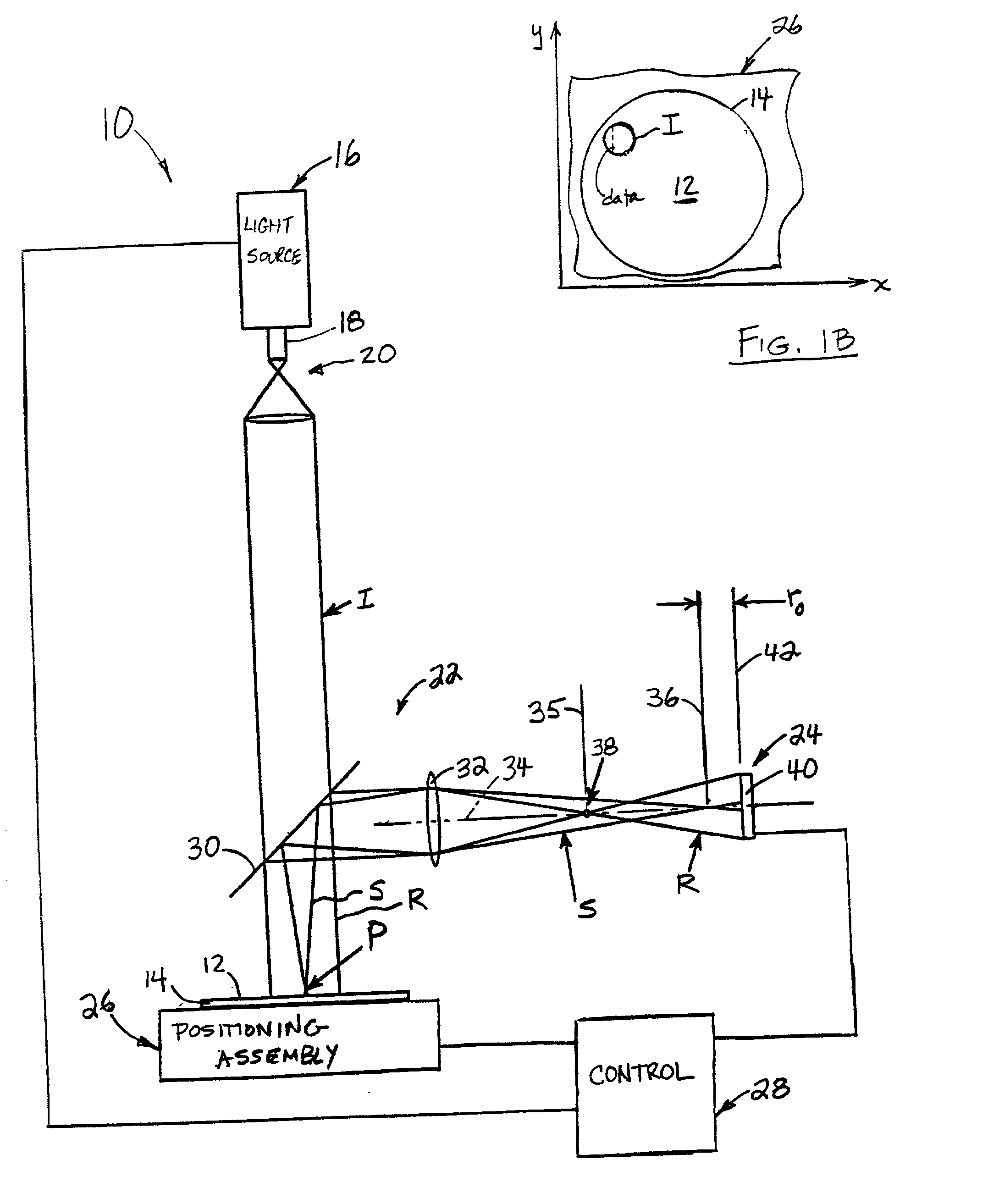
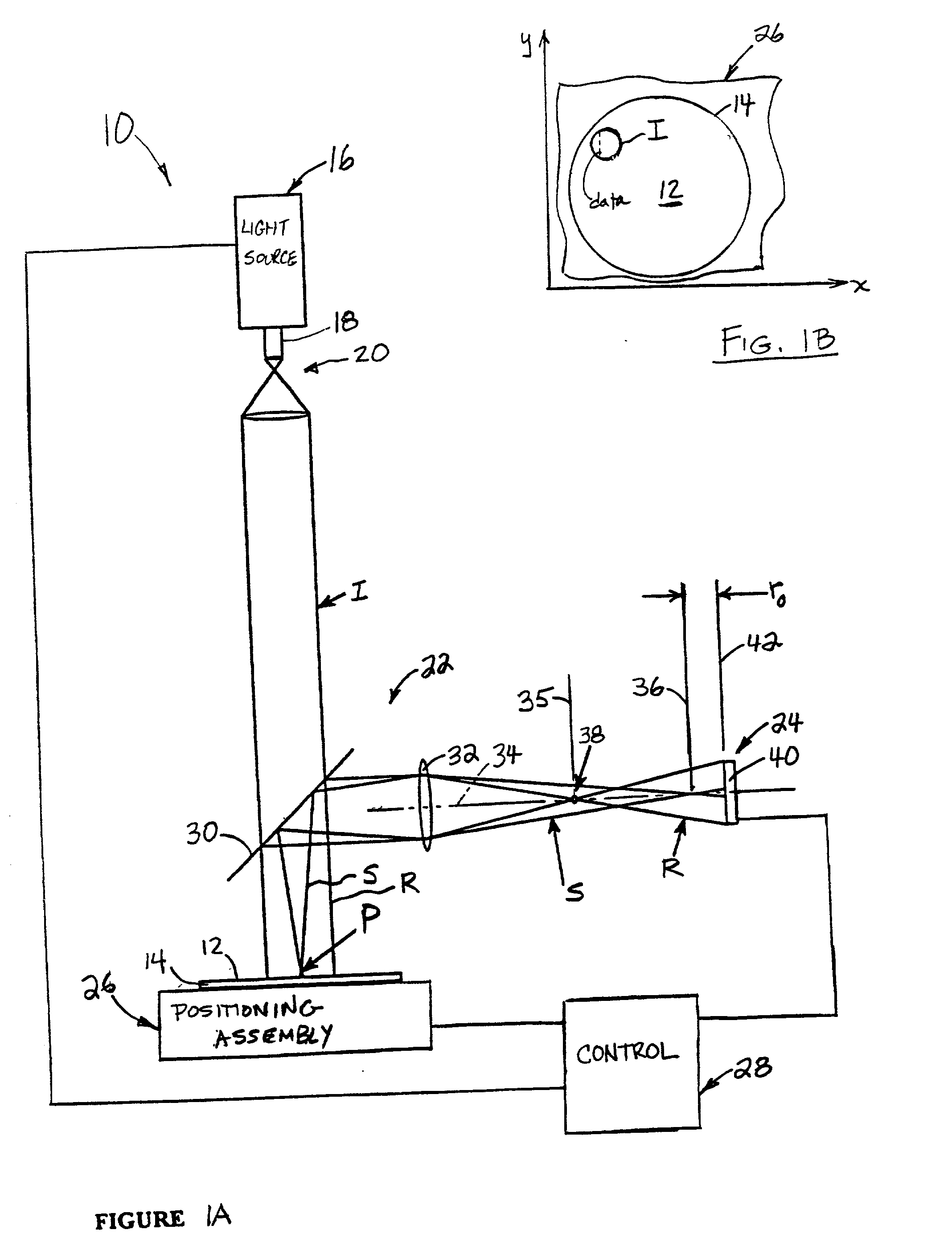
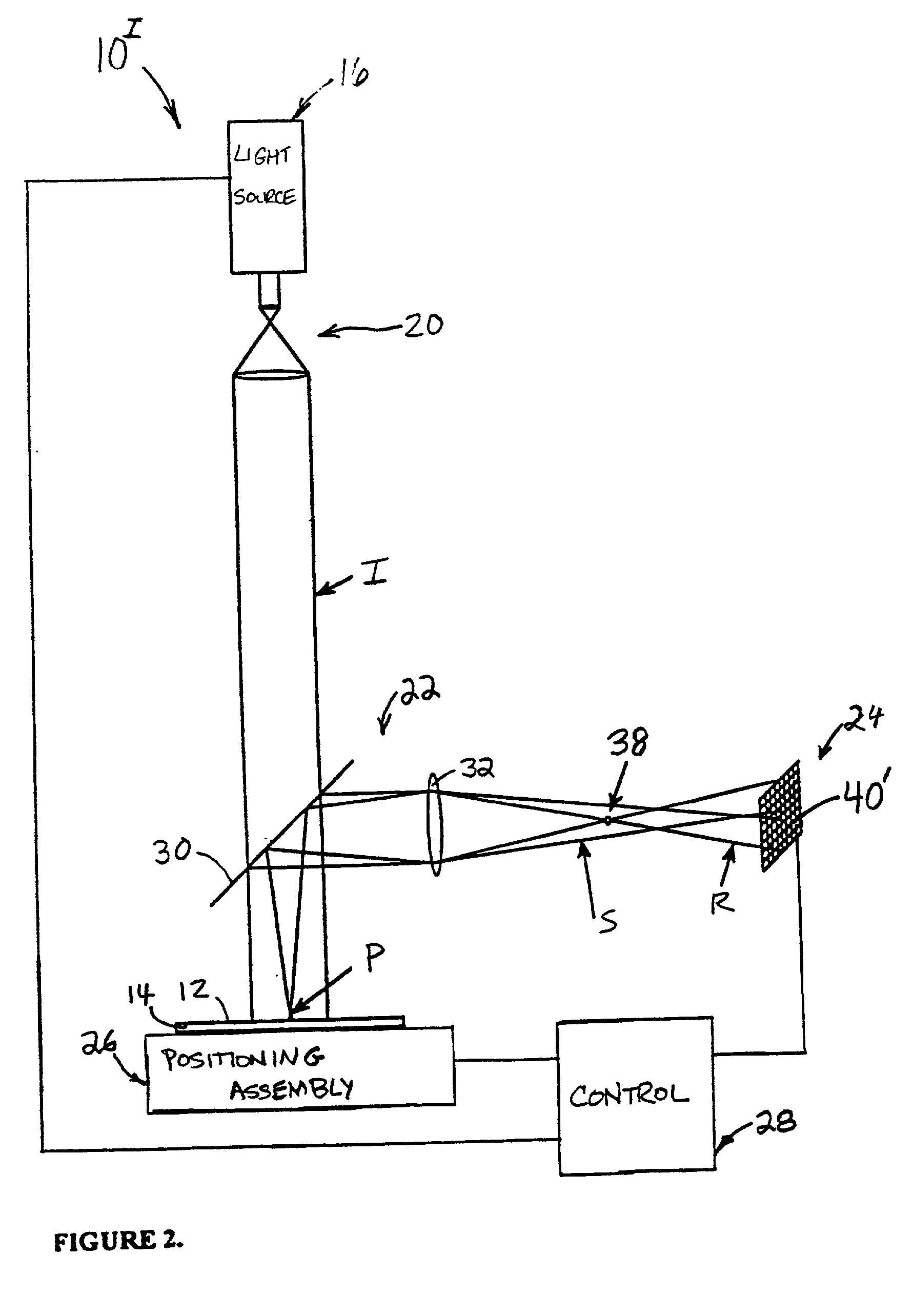
[0086] FIG. 9 shows an alternate, preferred, arrangement for the optical assembly 22 illustrated in FIGS. 1A, and 2-8. In particular, assembly 22' still includes beam splitter 30 and lens 32, but in addition further includes reflecting surfaces 70, 72, and 74. The advantage p...


PUM

PropertyMeasurementUnit
angleaaaaaaaaaa
diameteraaaaaaaaaa
particle sizeaaaaaaaaaa

Abstract

A holographic scatterometer with continuous readout can rapidly identify the presence of deposits (particles or other defects) on an unpatterned wafer surface and determine the volume density (size) and location. The scatterometer can also determine chemical composition of the detected deposits. The range of the deposit (particle) size to be measured is below 80 nm, which currently existing scatterometer type instruments cannot readily detect. The inspection can be achieved as an in-line stage during the processing of wafers or in situ in combination with another processing tool or as a separate off-line analysis device.

Description

[0002] 1. Technical Field[0003] This invention relates generally to optical inspection instruments and, more specifically, to such instruments that inspect a surface of interest, such as a wafer, for example during in-line processing.[0004] 2. Discussion of the Related Art[0005] There has been much investigation in the field of inspection systems. In particular, inspection systems are needed in the semiconductor industry for inspecting wafers. The significance for detecting and identifying submicron surface defects on such wafers is due in part to the present semiconductor industry move from 0.250 micron to 0.180 micron and, in less than ten years, to 0.130 micron fabrication architectures. The latter architecture is so exacting that it will require the detection of 2 nm substrate defects and 40 nm sized particles on unpatterned silicon wafers. In addition, the industry is scaling up from 200 mm to 300 mm diameter wafers with fewer defects commercially permitted, and rapid detection...

Claims


Application Information

Patent Timeline
Patent Type & Authority Applications(United States)
IPC IPC(8): G01N21/95
CPCG01N21/9501
Inventor KLOOSTER, ALEXMARKS, JAMES M.SAWATARI, TAKEO
Owner SENTEC CORP
Why Eureka
Try Eureka