Dedicated Network Diagnostics Module for a Process Network

a network diagnostic and process network technology, applied in the field of control system real-time distributed control, can solve the problems of network diagnostic tools, handheld tools that are not designed for permanent installation on the network, and limit the effective sensitivity and effectiveness of these devices, and achieve the effect of convenient user access

Inactive Publication Date: 2014-05-22
PHOENIX CONTACT DEVMENT & MFG
View PDF7 Cites 15 Cited by
  • Summary
  • Abstract
  • Description
  • Claims
  • Application Information

AI Technical Summary

Benefits of technology

[0018]Because the network diagnostic module is not a field device, the module can be installed on the network independently of the field devices. This enables the module to be coupled to the network almost anywhere along the network, including being spaced away from the field devices. Since the field devices are normally located at the end of spurs or branches of the network, this enables the network diagnostic module to be located at a point along the network better suited for obtaining network diagnostics or more convenient for user access.

Problems solved by technology

The diagnostic data is not transmitted back to the control processor over the communications network, and the handheld tool is not designed for permanent installation on the network.
Being adjacent the power supply places the tools far from the harsh operating environments where the field devices are located and where most faults and physical network problems occur, thereby limiting the effective sensitivity and effectiveness of these devices.
There are disadvantages in incorporating a network diagnostic tool in a field device.
A field device having an incorporated network diagnostic tool is more expensive than a field device without such a tool.
Furthermore, the network locations to which the network diagnostic tool can be attached are limited to only those network locations in which a field device can be attached, and so are limited to ends of spurs or branch connections.
These locations may not be optimal for network diagnostics.
Providing redundant diagnostic tools on the network can be expensive because more field devices with such tools must be provided, and the redundant diagnostic tools are separated along the network that may prevent locating the multiple diagnostic tools at optimum locations on the network.

Method used


Image

  • Dedicated Network Diagnostics Module for a Process Network
  • Dedicated Network Diagnostics Module for a Process Network
  • Dedicated Network Diagnostics Module for a Process Network

Examples


Embodiment Construction

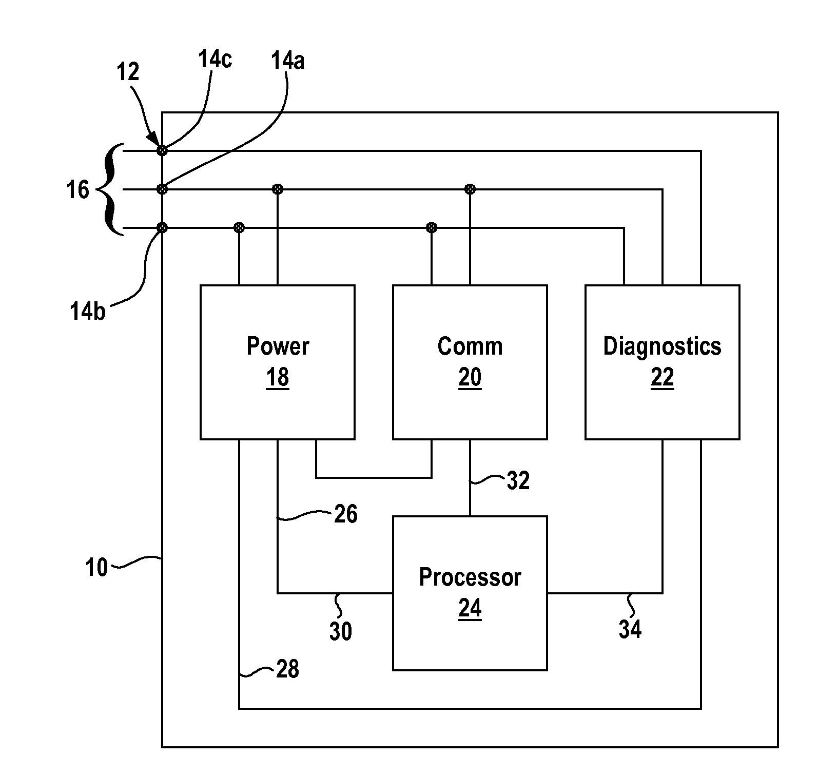
[0028]FIG. 1 illustrates a dedicated network diagnostic module in accordance with the present invention. The illustrated diagnostic module 10 is configured for use with a FOUNDATION™ Fieldbus H1 network and includes a trunk interface 12 for coupling the module 10 to the network. The illustrated trunk interface 12 includes two terminals 14a, 14b for connection to the F+ and F− wires of the two-wire trunk cable of the fieldbus network and a third terminal 14c for attaching to a shield wire if present. The diagnostic module 10 is shown with the terminals 14a, 14b, 14c connected to the signal, ground, and shield wires of a network trunk 16.

[0029]The diagnostic tool 10 includes a power block 18, a communications block 20, a diagnostic block 22, and a controller or processor 24.

[0030]The power block 18 draws electrical energy for the diagnostic module 10 from the network trunk 16 and provides power to the other blocks 20, 22, 24 and any additional internal components of the diagnostics mo...


PUM


Abstract

A network diagnostic module coupleable to a distributed process control network that controls an industrial process via field devices coupled to the network includes a power block coupleable to the network and configured to power the network diagnostic module with energy received from the network, a communications block coupleable to the network and configured to bi-directionally communicate over the network, and a diagnostics block coupleable to the network and configured to make diagnostic measurements of network and protocol parameters of the network. The network diagnostic module is not itself a field device that detects or controls any process variable of the industrial process, enabling the network diagnostic module to be placed essentially anywhere along the network to permanently monitor the network.

Description

FIELD OF THE INVENTION[0001]The invention relates to a control system for real-time distributed control, and more specifically, to a diagnostic device or module for the control system.BACKGROUND OF THE INVENTION[0002]Automated industrial systems have field devices that monitor, control, and operate an industrial process. Each field device detects or control process variables of the industrial process.[0003]The field devices communicate with a control processor or head through a trunk that transmits power to the field devices and transmits data signals (which can include operating commands) between the control processor and the field devices. The field devices each attach to the trunk via a spur or branch connection. The field devices can be distributed throughout the industrial plant, and the data transmittal rates allow essentially real-time control of the process.[0004]Standardized network configurations such as Fieldbus or Profibus PA™ have been developed for distributed control ...

Claims


Application Information

Patent Timeline
Patent Type & Authority Applications(United States)
IPC IPC(8): G06F11/07
CPCG06F11/079G06F11/30H04L12/40045H04L12/6418H04L41/082H04L2012/40221H04Q9/00H04Q2209/30H04Q2209/75H04Q2209/823Y04S40/162Y04S40/00
Inventor VOGT, BRIANHELFRICK, BRENTON EUGENEKREIDER, AARON RICHARDMATHEWS, DAVIS
Owner PHOENIX CONTACT DEVMENT & MFG
Why Eureka
Try Eureka