System and method for waste heat recovery for internal combustion engines

Inactive Publication Date: 2014-05-29
SPICER OFF HIGHWAY BELGIUM
View PDF4 Cites 15 Cited by
  • Summary
  • Abstract
  • Description
  • Claims
  • Application Information

AI Technical Summary

Benefits of technology

[0006]Presently provided by the invention, a driveshaft that may be formed using a hydroforming process,

Problems solved by technology

A conventional internal combustion engine typica

Method used


Image

  • System and method for waste heat recovery for internal combustion engines
  • System and method for waste heat recovery for internal combustion engines
  • System and method for waste heat recovery for internal combustion engines

Examples


Embodiment Construction

[0014]It is to be understood that the invention may assume various alternative orientations and step sequences, except where expressly specified to the contrary. It is also to be understood that the specific devices and processes illustrated in the attached drawings, and described in the following specification are simply exemplary embodiments of the inventive concepts defined herein. Hence, specific dimensions, directions or other physical characteristics relating to the embodiments disclosed are not to be considered as limiting, unless expressly stated otherwise.

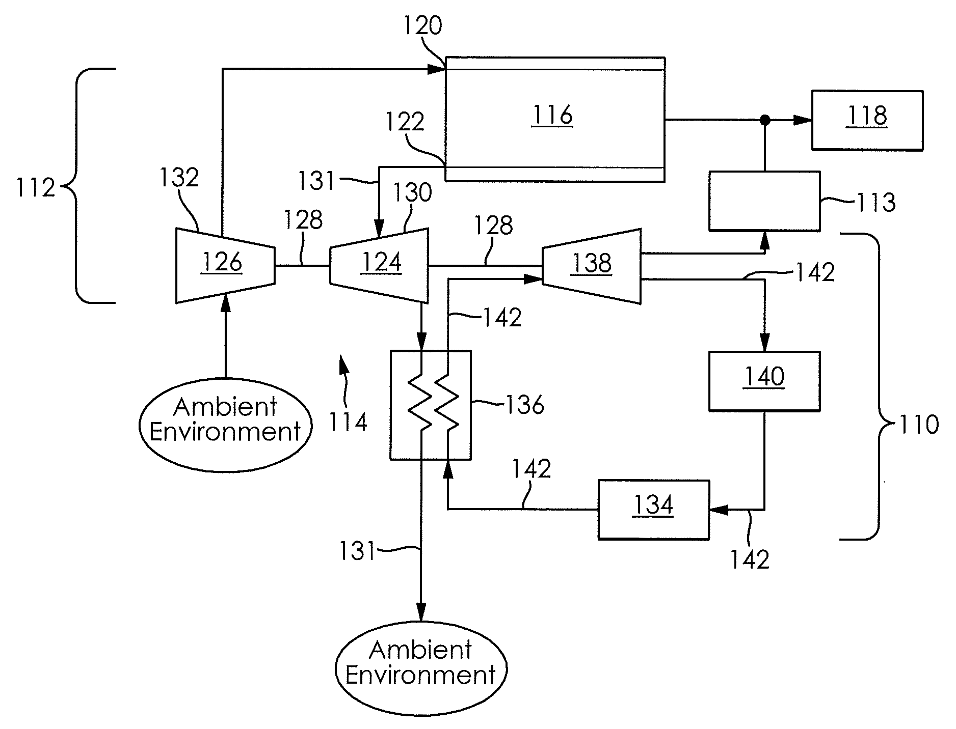
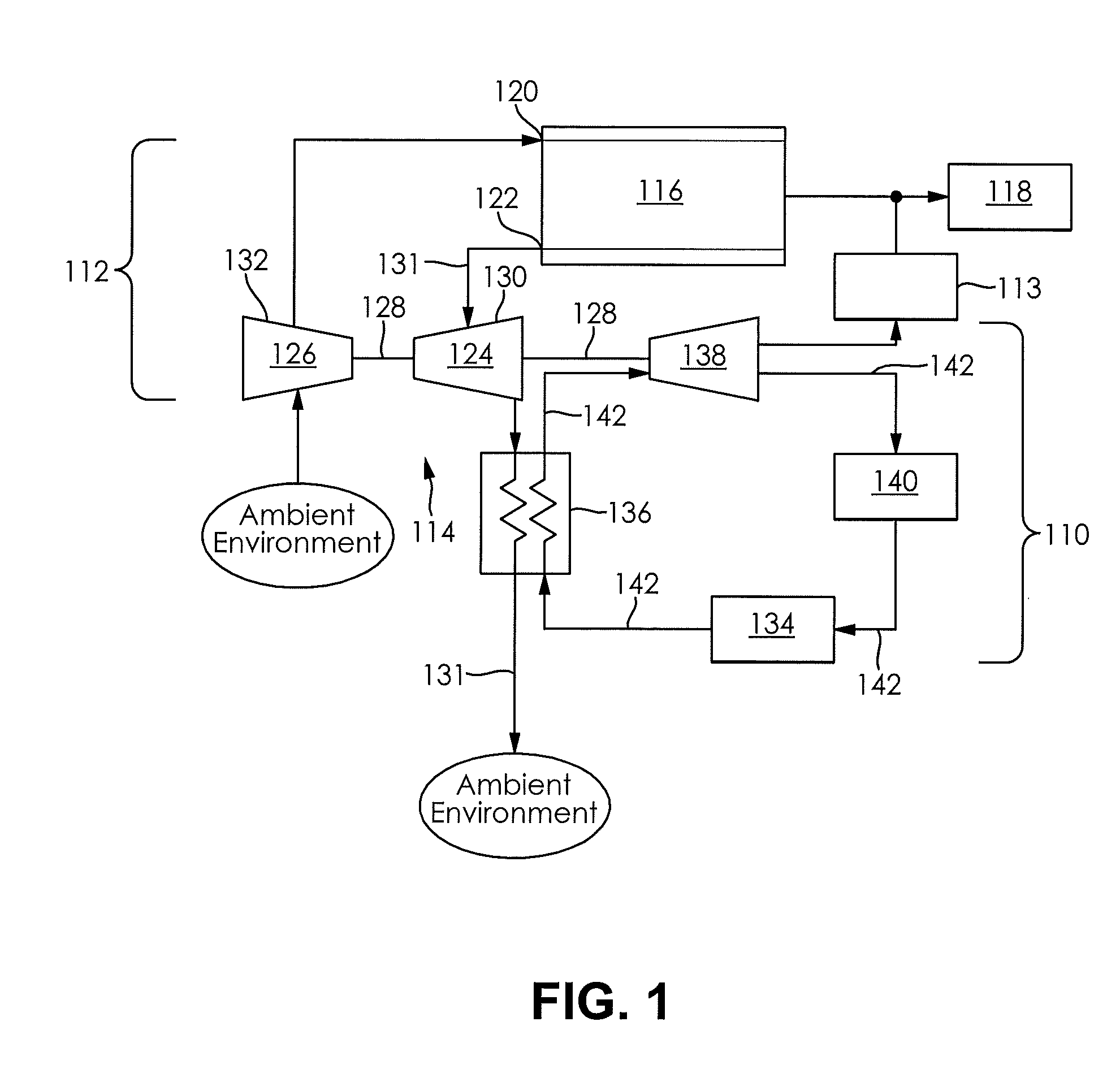
[0015]FIG. 1 schematically illustrates a waste heat recovery (WHR) system 110 for use with an internal combustion engine 112. The WHR system 110 is in driving engagement and fluid communication with the internal combustion engine 112. A portion of the WHR system 110 is in driving engagement with a portion of the internal combustion engine 112 through a ratio adapting device 113. The WHR system 110 may utilize the organic R...


PUM


Abstract

A combined internal combustion engine and waste heat recovery system is provided. The combined internal combustion engine and waste heat recovery system comprises the internal combustion engine, the waste heat recovery system, and a ratio adapting device. The internal combustion engine includes a turbocharger. The waste heat recovery system comprises a condenser, a pump, a heat exchanger, and an expander. The expander is in driving engagement with the turbocharger. The ratio adapting device is drivingly engaged with an output of the internal combustion engine and the expander of the waste heat recovery system. The ratio adapting device may be engaged to transfer energy from at least one of the turbocharger and the expander to the output of the internal combustion engine.

Description

CLAIM OF PRIORITY[0001]The present application claims the benefit of priority to U.S. Provisional Application No. 61 / 730,645 filed on Nov. 28, 2012, which is incorporated herein in its entirety by reference.FIELD OF THE INVENTION[0002]The present invention relates to energy recovery systems and more specifically to waste heat recovery systems used with internal combustions engines.BACKGROUND OF THE INVENTION[0003]A conventional internal combustion engine typically has a limited brake thermal efficiency (BTE). Energy released during a combustion process utilized by the internal combustion engine is only partially converted to useful work. A large portion of the energy released during the combustion process is rejected as waste heat to an ambient environment of the internal combustion engine. The waste heat is typically dispersed to the ambient environment of the internal combustion engine through the use of a cooling system and an exhaust system of the internal combustion engine. Eff...

Claims


Application Information

Patent Timeline
IPC IPC(8): F02B37/00
CPCF02G5/02F02B41/10F01N5/02F02B39/085F02B37/10F02B37/105Y02T10/12
Inventor VERSTEYHE, MARK R.J.
Owner SPICER OFF HIGHWAY BELGIUM
Why Eureka
Try Eureka