
Hot Stamping System And Method

a technology of hot stamping and parts, applied in the field of system and method for hot stamping a plurality of parts, can solve the problem of increasing the cost per part produced by the system

Active Publication Date: 2014-05-29
MAGNA INTERNATIONAL INC
View PDF4 Cites 29 Cited by
  • Summary
  • Abstract
  • Description
  • Claims
  • Application Information

AI Technical Summary

Benefits of technology

This patent describes a system and method for hot forming multiple parts, such as steel components for automobiles. The system includes a furnace with multiple vertical shelves for conveying blanks through the furnace, heated by adjacent heaters. The shelves and heaters can be easily removed for maintenance. The system also includes a hot forming apparatus for shaping the heated blanks, and a blank feeder for conveying the blanks from the furnace to the hot forming apparatus. The technical effect of this invention is the ability to efficiently produce multiple parts simultaneously, with the ability for easy maintenance and replacement of malfunctioning heaters.

Problems solved by technology

However, when the furnace malfunctions, the entire system must be shut down for a period of time while the furnace is repaired, which increases the cost per part produced by the system.

Method used


Image

  • Hot Stamping System And Method
  • Hot Stamping System And Method
  • Hot Stamping System And Method

Examples


Embodiment Construction

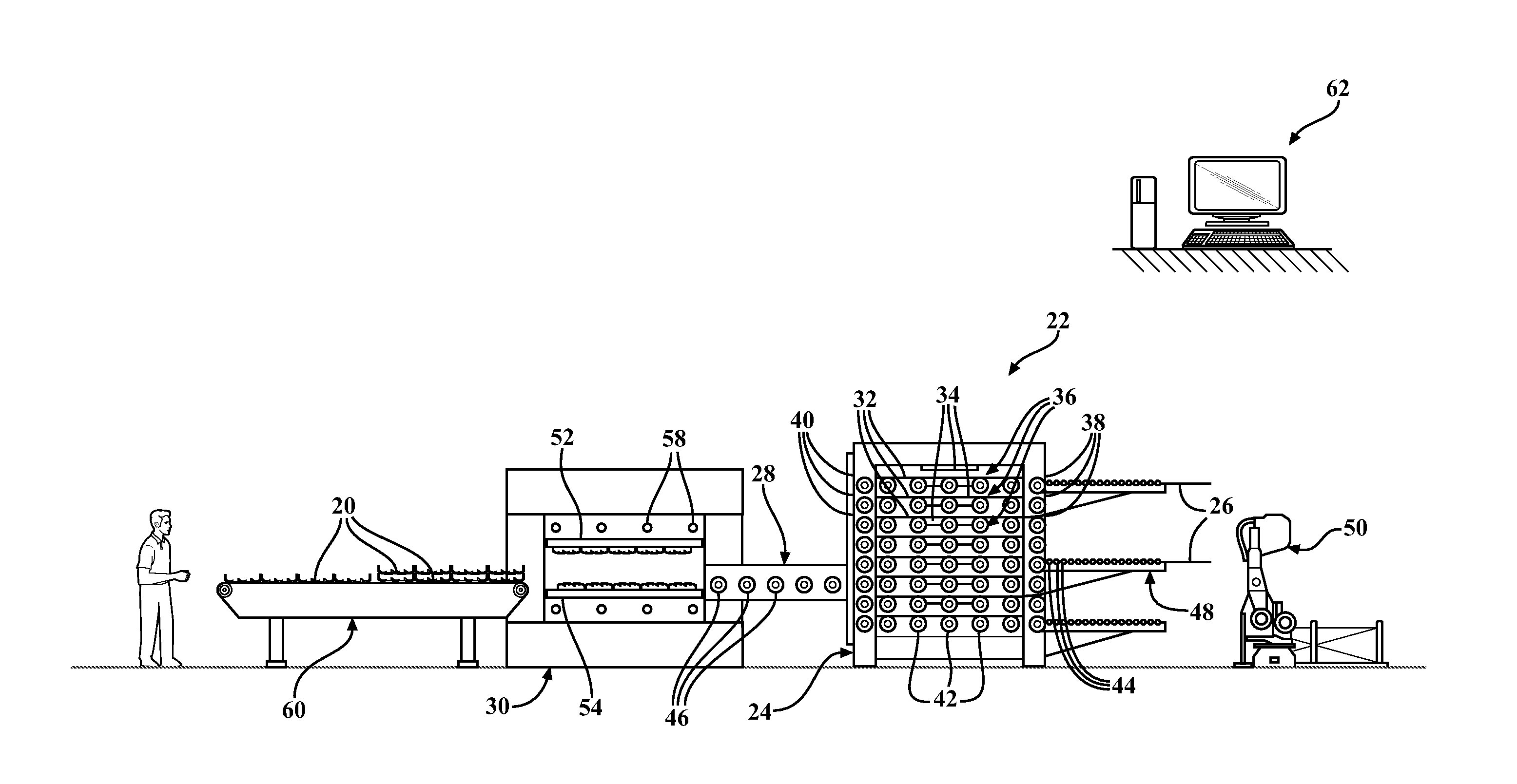
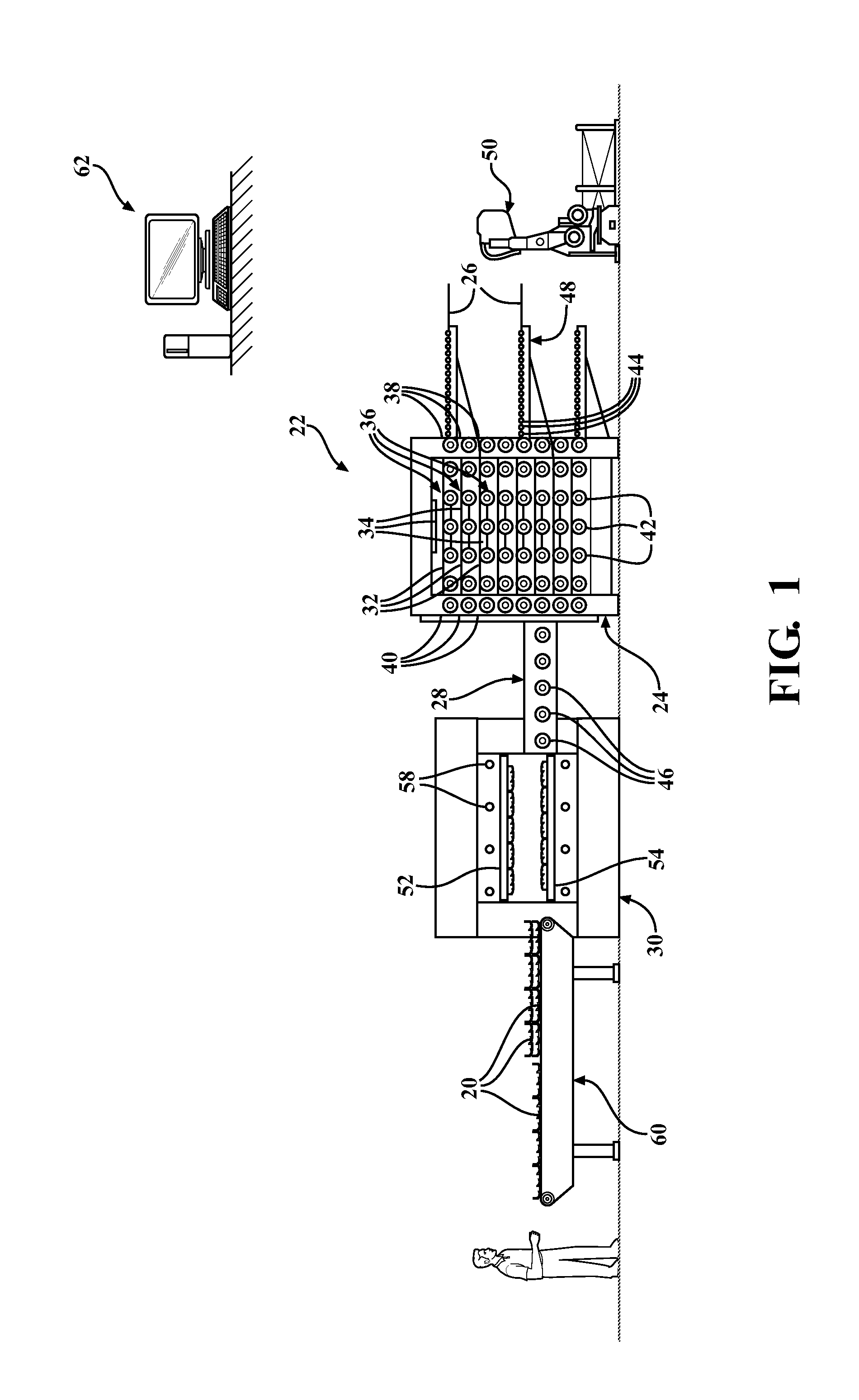
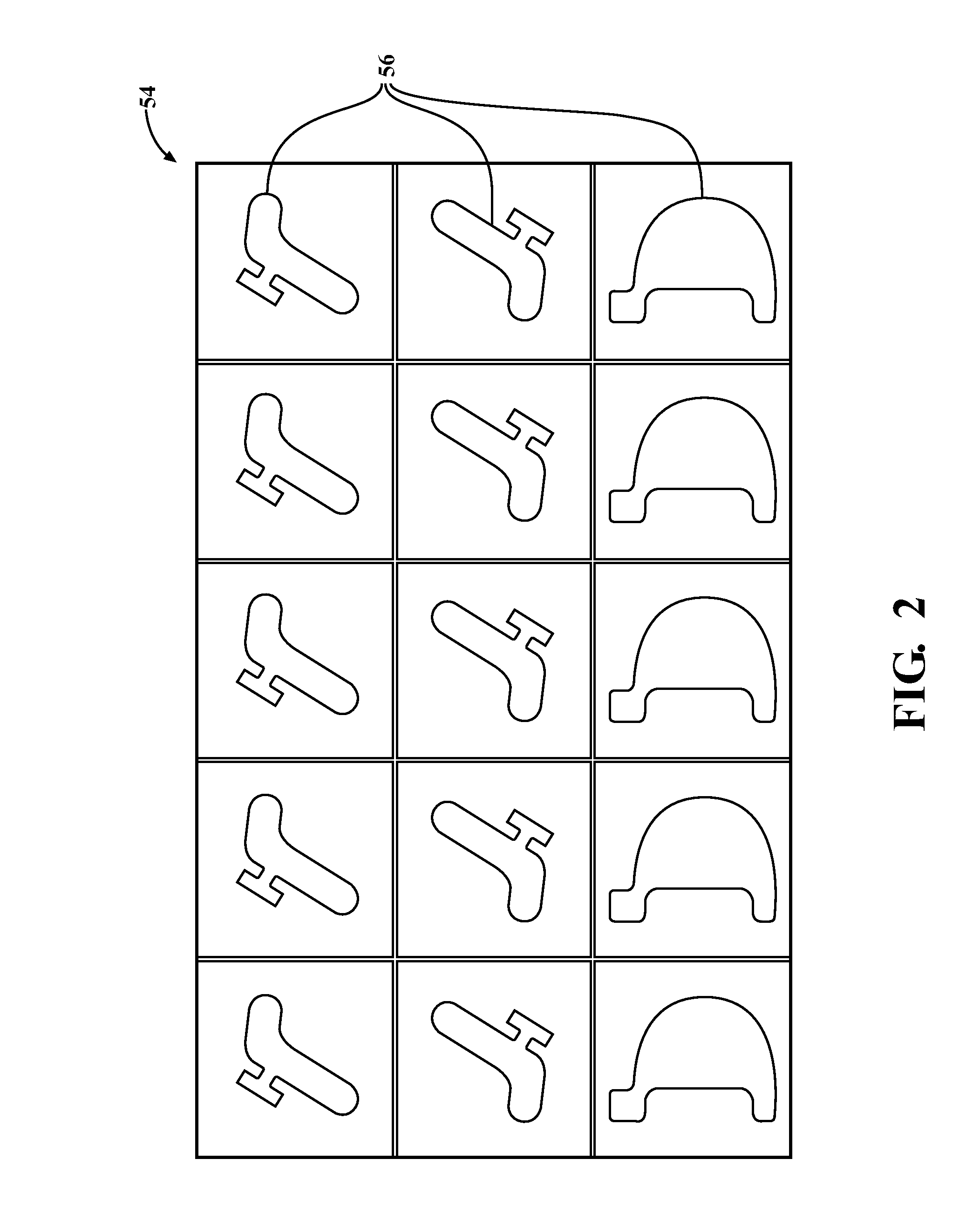
[0011]Referring to the Figures, wherein like numerals indicate corresponding parts 20 throughout the several views, an exemplary system 22 for hot forming a plurality of shaped parts 20 is generally shown in FIG. 1. The system 22 includes a furnace 24 for heating a plurality of blanks 26, a hot forming apparatus 30 for shaping the heated blanks 26, and a blank feeder 28 for conveying the heated blanks 26 from the furnace 24 to the hot forming apparatus 30. The system 22 provides reduced down time and thus reduced overhead costs per part 20, compared to other hot forming systems. The system 22 also requires less floor space compared to the other systems.

[0012]The blanks 26 used to manufacture the shaped parts 20 are typically formed of metal, but can be formed of other materials. In one exemplary embodiment, the blanks 26 are formed of steel material, such pure steel or a steel alloy. Although the shaped parts 20 are typically designed for use as chassis or automotive body components...


PUM

PropertyMeasurementUnit
Temperatureaaaaaaaaaa
Heataaaaaaaaaa

Abstract

A system for forming a plurality of hot stamped steel parts for automotive applications includes a furnace with a stack of sealed chambers, each containing an individual heater, for simultaneously heating a plurality of blanks. Each chamber is removable from the furnace, so that if the heater contained therein malfunctions, the heater can be repaired while the other chambers continue to heat the blanks. Each chamber also comprises a shelf including a plurality of driven rollers for conveying the blanks through the furnace. A blank feeder also including a plurality of driven rollers extends continuously from the furnace to a hot forming apparatus. The hot forming apparatus includes a plurality of cavities for shaping one or more of the blanks into a plurality of the parts.

Description

CROSS REFERENCE TO RELATED APPLICATION[0001]This U.S. patent application claims the benefit of U.S. Provisional Patent Application Ser. No. 61 / 730,667 filed Nov. 28, 2012, entitled “Hot Stamping System And Method,” the entire disclosure of the application being considered part of the disclosure of this application and hereby incorporated by reference.BACKGROUND OF THE INVENTION[0002]1. Field of the Invention[0003]The inventions relates generally to a system and method for hot forming a plurality of parts, such as steel parts for chassis and automotive body applications.[0004]2. Related Art[0005]Hot forming processes typically comprise heating a steel blank in a furnace, followed by stamping the heated blank between a pair of dies to form a shaped part, and quenching the shaped part between the dies. The steel blank is typically heated in the furnace to achieve an austenitic microstructure, and then quenched in the dies to transform the austenitic microstructure to a martensitic micr...

Claims


Application Information

Patent Timeline
IPC IPC(8): B21D22/02
CPCB21D22/022B21D43/08C21D1/673C21D9/005F27B9/024F27B9/2407B21D35/00B21D37/16B21D53/88
Inventor POTOCKI, JOHN RICHARDWISEMAN, TAD STEWART
Owner MAGNA INTERNATIONAL INC
Features
  • Generate Ideas
  • Intellectual Property
  • Life Sciences
  • Materials
  • Tech Scout
  • Unparalleled Data Quality
  • Higher Quality Content
  • 60% Fewer Hallucinations
Learn More