Tray and an image forming apparatus provided with the tray

a technology of image forming apparatus and tray, which is applied in the direction of transportation and packaging, thin material processing, and article separation, etc., can solve problems such as collision noise, and achieve the effect of reducing collision nois

Active Publication Date: 2014-05-29
KONICA MINOLTA INC
View PDF0 Cites 7 Cited by
  • Summary
  • Abstract
  • Description
  • Claims
  • Application Information

AI Technical Summary

Benefits of technology

[0008]An object of the present invention is to provide a tray that can reduce collision noise occurring with a draw of the tray, and an image forming apparatus provided with the tray.

Problems solved by technology

Publication No. 2006-8291 has a problem that it makes a collision noise when drawn from the body of the image forming apparatus.

Method used


Image

  • Tray and an image forming apparatus provided with the tray
  • Tray and an image forming apparatus provided with the tray
  • Tray and an image forming apparatus provided with the tray

Examples


first modification

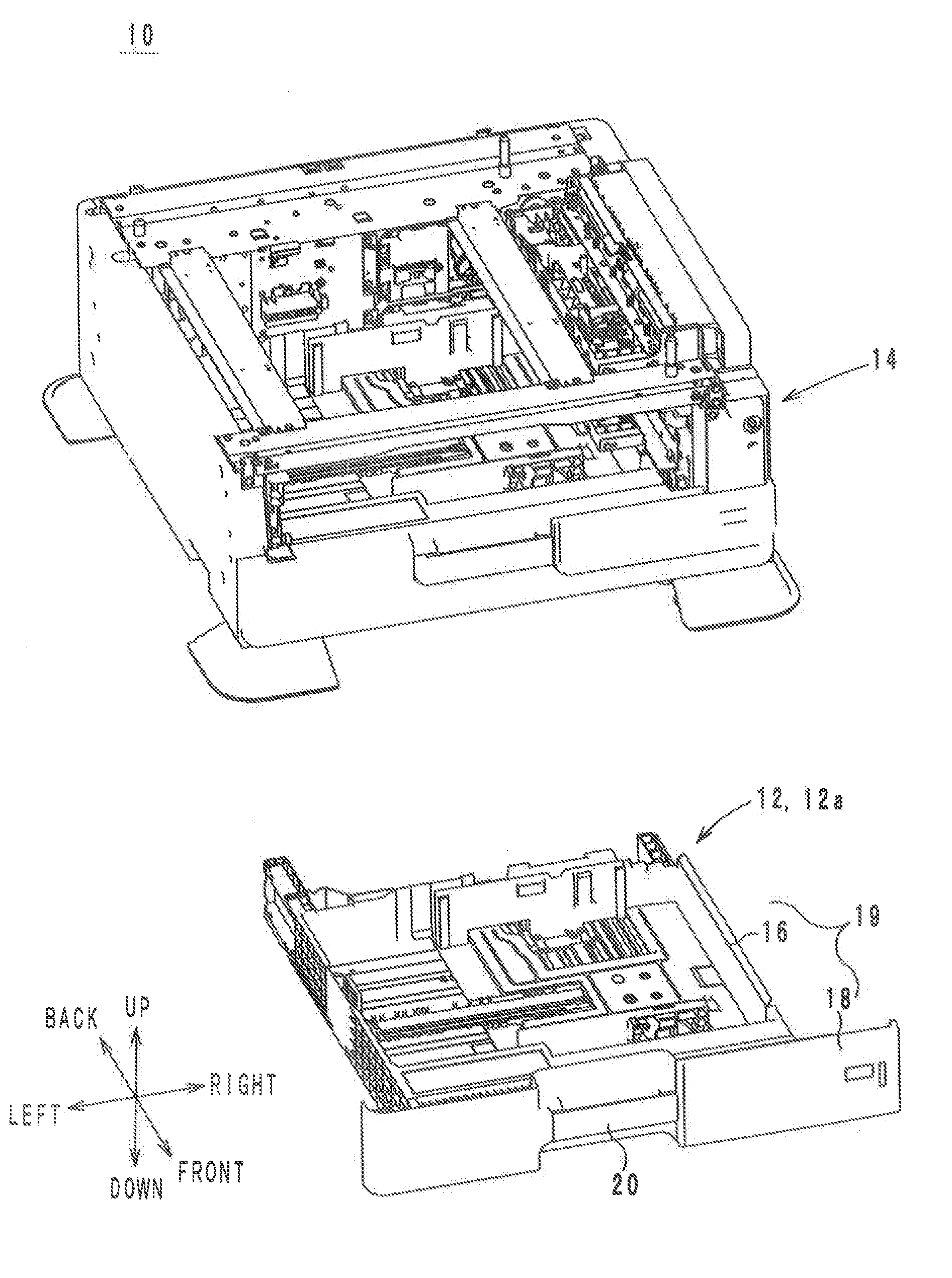
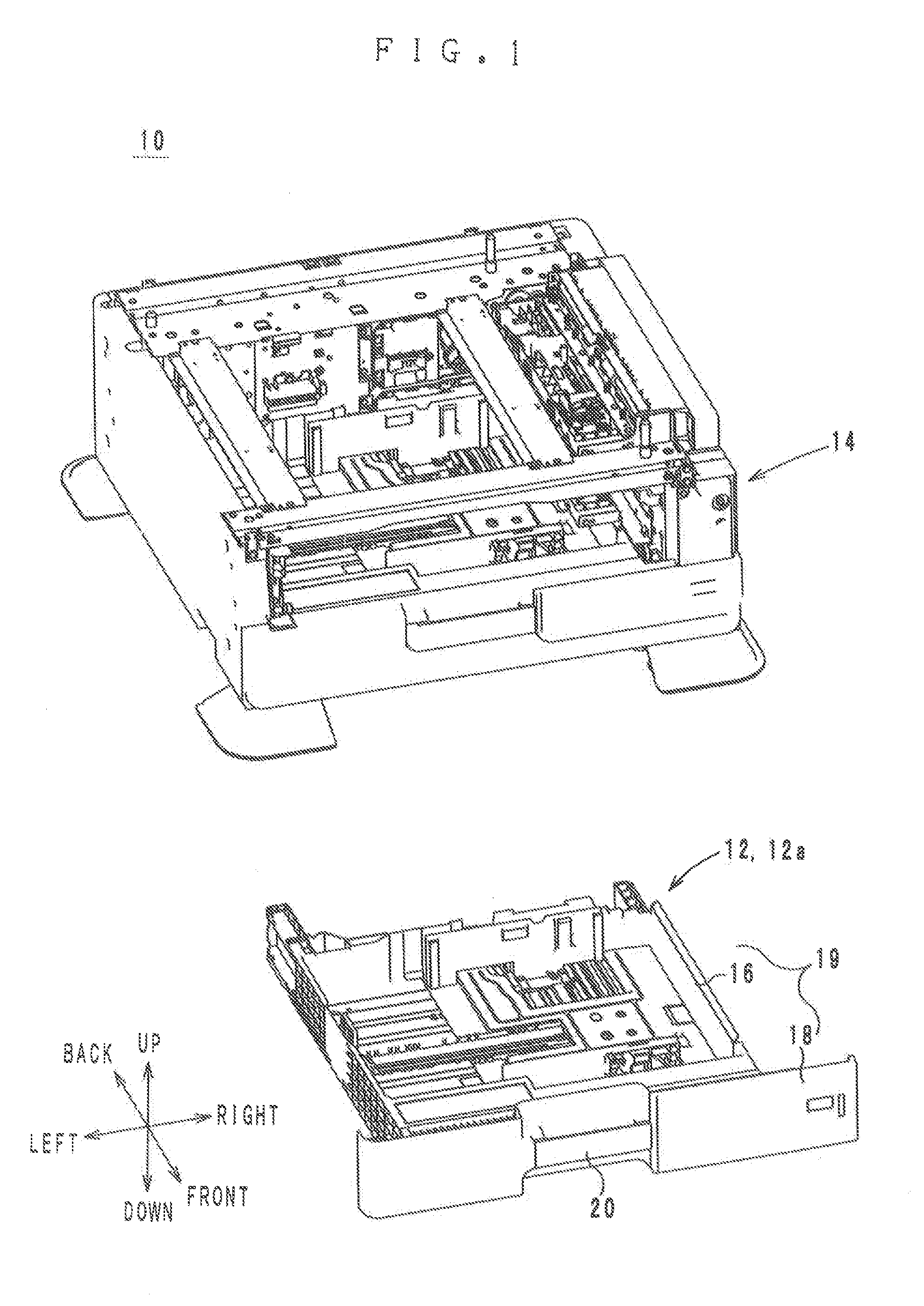
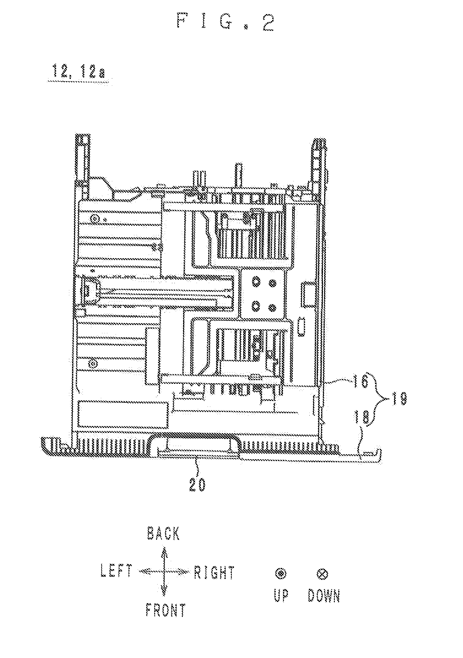
[0046]A tray 12a according to a first modification is described below with reference to the accompanying drawings. FIG. 7 shows the structure of the front cover 18 of the tray 12a according to the first modification. FIG. 8 shows the front cover 18 in a state where the handle 20 of the tray 12 is pulled diagonally. The general structure of the tray 12a is shown by FIGS. 1 and 2.

[0047]The tray 12a is different from the tray 12 in positions of the elastic members 24 and 26. More specifically, in the tray 12, the elastic members 24 and 26 are located between the contact portions P1 and P2. In the tray 12a, however, the contact portions F1 and P2 are located between the elastic members 24 and 26. As will be described below, this arrangement ensures a reduction of collision noise even if the handle 20 is pulled diagonally.

[0048]In the tray 12, when the handle 20 is pulled diagonally, the handle 20 tilts as shown in FIG. 8, and the contact part 204 tilts, so that the contact portion P1 of...


PUM


Abstract

A tray drawable from an image forming apparatus body in a specified first direction, the tray having: a tray body in which printing media are stored; a handle that is fastened to the tray body so as to be slidable in the first direction by a specified distance, a pull of the handle in the first direction effecting a slide of the handle in the first direction relative to the tray body and applying a pull force in the first direction to the tray body; a lock mechanism for locking the tray body in the image forming apparatus body, the slide of the handle in the first direction relative to the tray body cancelling the lock mechanism; and an elastic member located between the handle and the tray body; wherein at least part of the pull force is transmitted from the handle to the tray body via the elastic member.

Description

[0001]This application is based on Japanese Patent Application No. 2012-259852 filed on Nov. 28, 2013, the content of which is herein incorporated by reference.BACKGROUND OF THE INVENTION[0002]1. Field of the Invention[0003]The present invention relates to a tray and an image forming apparatus provided with the tray, and more particularly to a tray that is constructed to be drawable in a specified first direction from the body of an image forming apparatus, and an image forming apparatus provided with the tray.[0004]2. Description of Related Art[0005]As a conventional tray, there is known, for example, a lockable storage cassette (which will be referred to as storage cassette) disclosed by Japanese Patent Laid-Open Publication No. 2006-8291. FIG. 10 is an exploded perspective view of a handle 500 of the storage cassette disclosed by Japanese Patent Laid-Open Publication No. 2006-8291.[0006]The handle 500 is a part of the storage cassette, and comprises a grip 520, a support 521, bol...

Claims


Application Information

Patent Timeline
Patent Type & Authority Applications(United States)
IPC IPC(8): B65H1/04
CPCB65H1/04B65H1/266B65H2403/60B65H2405/121B65H2405/32
Inventor NAOI, SHINYA
Owner KONICA MINOLTA INC
Why Eureka
Try Eureka