Multi-Channel Pipette

a pipette and multi-channel technology, applied in the field of multi-channel pipette, can solve the problems of limited clamping force of pipette tips, affecting and requiring significant effort to remove the pipette tip from the spigot, so as to reduce the effort for the actuation of ejection equipment

Active Publication Date: 2014-05-29
EPPENDORF SE
View PDF7 Cites 19 Cited by
  • Summary
  • Abstract
  • Description
  • Claims
  • Application Information

AI Technical Summary

Benefits of technology

[0014]Starting from this, the present invention is based on the task to provide a multichannel pipette which further reduces the effort for the actuation of the ejection equipment.
[0029]In the starting position, the first and second take-along means of the ejector are in a distance from each other. In the downward dislocation of the ejector, the first and the second ejector part are dislocatable relative to each other in the longitudinal direction of the spigots. The dislocation of the ejector parts with respect to each other is limited by the impingement of the first and second take-along means on each other. When the first contact element impinges on the pipette tips in the downward dislocation of the ejector, the second contact element is prevented from a further downward dislocation by the pipette tips at first. As a consequence, only the first ejector part continues the downward dislocation and squeezes pipette tips off from the lugs. In this, the first ejector part is dislocated relative to the second ejector part, until the first take-along means hit the second take-along means. Thereafter, the first ejector part takes the second ejector part downward along, which squeezes pipette tips off from the spigots by the second contact element. Thus, several pipette tips ore several groups of pipette tips are consecutively ejected from the spigots and the maximum force for ejecting the pipette tips is reduced.
[0031]According to one embodiment, the distance between the first and second take-along means in the vertical direction is 0.1 to 3 mm, preferably 0.5 to 1.5 mm in the starting position of the ejector. This distance is sufficient for squeezing off different pipette tips or different groups of pipette tips subsequently by means of the ejector, and it can be realised without sensibly increasing the ejection stroke.
[0032]According to a further embodiment, the first ejector part has a first deepening on its lower edge with first guide elements on two lateral edges, and the second ejector part is inserted into the first deepening of the first ejector part and is dislocatable in the longitudinal direction of the spigots on second guide elements on two lateral edges on the first guide elements of the first ejector part. The first and second ejector parts are preferably board-shaped in this. By guiding the second ejector part on two lateral edges of the first deepening, it is ensured that the second ejector part is smoothly dislocatable with respect to the first ejector part.
[0034]According to a further embodiment, the second ejector part is held on the first ejector part by connection means which have a clearance in the longitudinal direction of the spigots. The second ejector part is undetachably connected to the first ejector part by the connection means, so that it cannot release itself from the bottom side of the multichannel pipette. According to a further embodiment, the connection means are snap connection means. The connection of the ejector parts by (snap-) connection means is advantageous for the mounting.
[0035]According to a further embodiment, the snap connection means have an eyelet on the first ejector part, and a snap hook engaging with clearance in the direction of the spigots into the eyelet on the second ejector part or vice versa. By these snap connection means, the snap connection can be implemented particularly simply and safely.

Problems solved by technology

Detaching a pipette tip from the spigot can necessitate a significant effort when a pipette tip is to be firmly clamped up on a spigot.
The clamping force of the pipette tips is limited by this.

Method used


Image

  • Multi-Channel Pipette
  • Multi-Channel Pipette
  • Multi-Channel Pipette

Examples


Embodiment Construction

[0077]While this invention may be embodied in many different forms, there are described in detail herein a specific preferred embodiment of the invention. This description is an exemplification of the principles of the invention and is not intended to limit the invention to the particular embodiment illustrated.

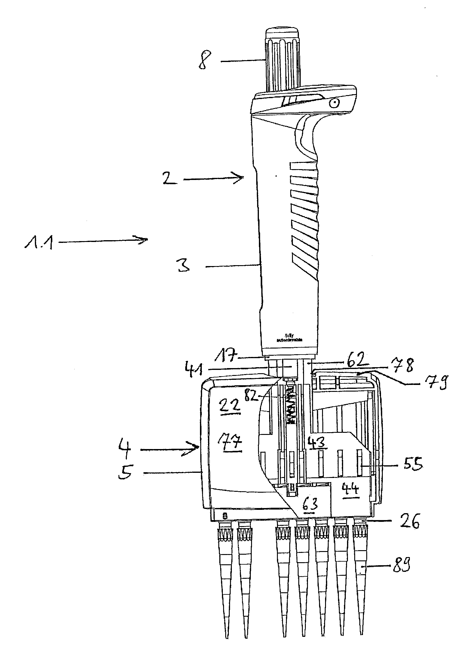
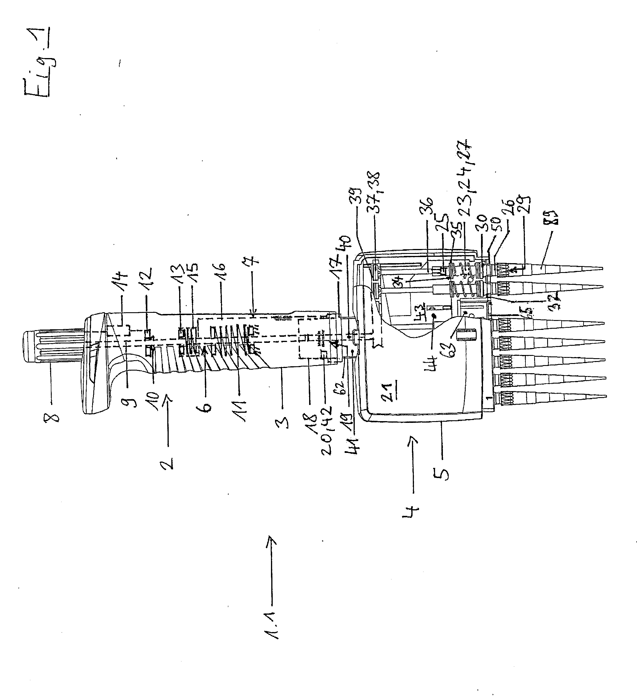
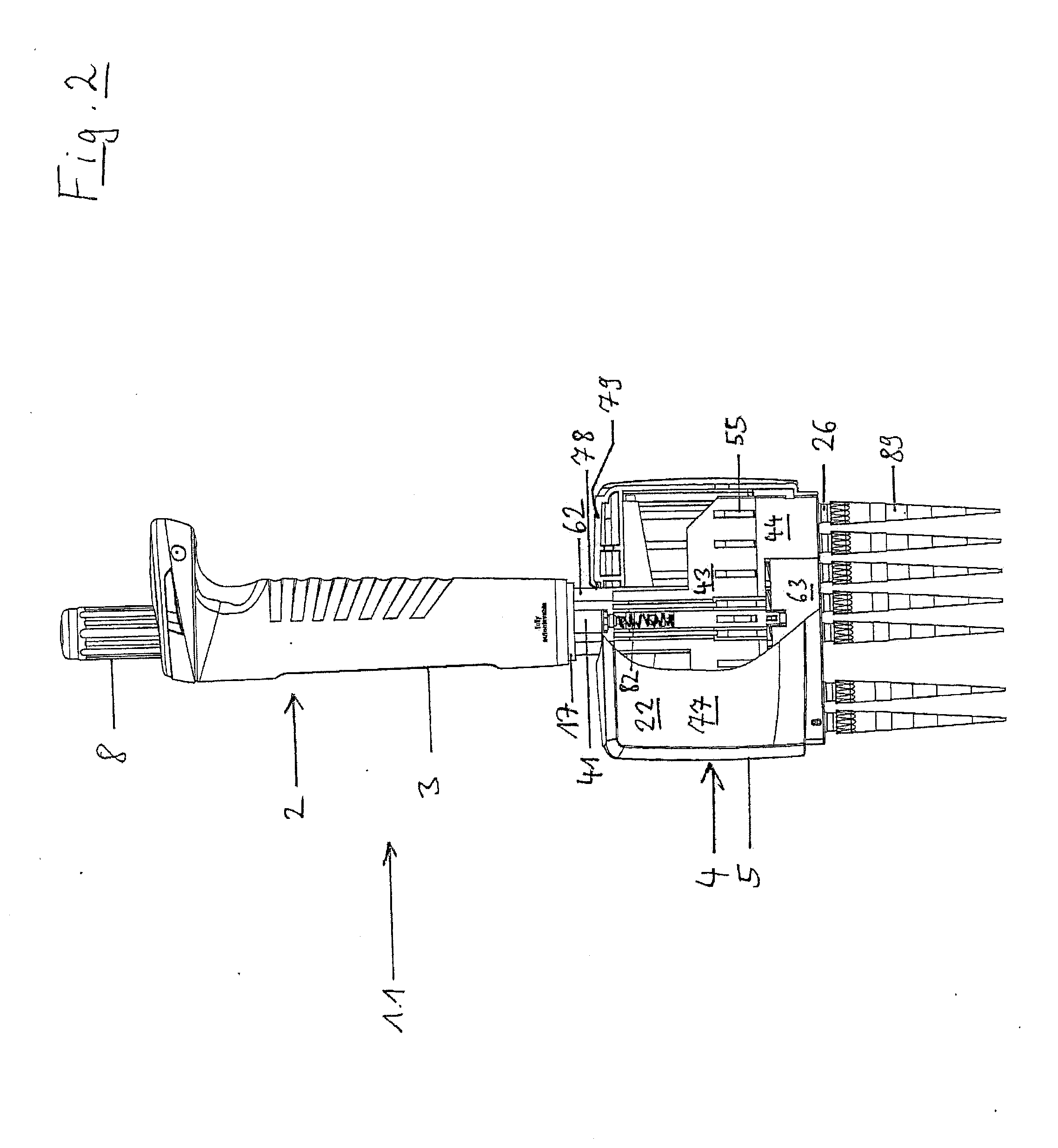
[0078]In the present application, the designations “up” and “down”, “in the same height” as well as “horizontal” and “vertical” refer to an arrangement of the multichannel pipette wherein the pipette tips clamped onto the spigots are aligned vertically and with their syringe openings downward, in order to pick up a liquid from a vessel arranged underneath or to deliver it into the vessel.

[0079]All realisation examples refer to multichannel pipettes wherein the contact elements of the ejector are stop elements at the same time. Below, the contact elements are designated as stop elements.

[0080]According to FIGS. 1 and 2, a multichannel pipette 1.1 has a pipette upper part 2 wit...


PUM


Abstract

A multichannel pipette with a base body, several spigots for clamping up pipette tips, arranged parallel side by side in a row, protruding from the base body and mounted on the base body so as to be movable in their longitudinal direction, at least one displacement equipment with a displacement chamber and a displacement member dislocatable therein, wherein the displacement chamber is connected to connection holes in the spigots in order to eject or aspirate air through openings of the connection holes in lower ends of the spigots, a first drive device, connected to the displacement member and adapted to dislocate the displacement member in the displacement chamber, first spring elements, engaging on the spigots and on the base body, wherein the spigots are dislocatable upward in their longitudinal direction from a starting position against the spring action of the first spring elements.

Description

CROSS-REFERENCE TO RELATED APPLICATIONS[0001]This application claims priority to 61 / 729,466 filed on Nov. 23, 2012STATEMENT REGARDING FEDERALLY SPONSORED RESEARCH[0002]Not applicable.BACKGROUND OF THE INVENTION[0003]The present invention relates to a multichannel pipette with several spigots (“lugs”) for clamping up pipette tips and an ejection equipment for detaching pipette tips from spigots.[0004]Pipettes are used for dosing liquids, notably in medical, biological, biochemical, chemical and other laboratories. The liquids are picked up and delivered in pipette tips through a tip opening. In air cushion pipettes, a displacement equipment for air is integrated into the pipette and communicatingly connected to the pipette tip through a connection hole of the spigot. An air cushion can be dislocated by means of the displacement equipment, so that liquid is sucked into the pipette tip and ejected out from there. The displacement equipment is mostly a cylinder with a piston that can be...

Claims


Application Information

Patent Timeline
Patent Type & Authority Applications(United States)
IPC IPC(8): B01L3/02
CPCB01L3/0279B01L2200/0605B01L2200/087
Inventor SCHMIDT, PETER
Owner EPPENDORF SE
Why Eureka
Try Eureka