
Real-Time Monitoring System to Determine Wear of Grate Ribs in Semi-Autogenous Mills, to Detect Clogging Conditions of the Grates During the Operation and to Detect Working Conditions Under Direct Impact of the Balls on the Grates

Active Publication Date: 2014-06-05
UNIV DE SANTIAGO DE CHILE
View PDF6 Cites 14 Cited by
  • Summary
  • Abstract
  • Description
  • Claims
  • Application Information

AI Technical Summary

Benefits of technology

The invention is a monitoring system for a SAG mill that can detect the thickness of the ribs, any impacts on the grates, and obstruction in the slots of the grates while the mill is in operation. The system can also detect when the balls hit the grates directly and take appropriate actions to remove or minimize this condition.

Problems solved by technology

During a SAG mill operation as with other components within thereof, the grates experience wearing due to the movement of the internal load which generates abrasive actions on the liners as well as direct impacts from the elements used for the grinding operation, i.e., the steel balls.
This condition might result in the impacts between balls and the grate produce an even greater wearing than the usual or that they reach a level of structural resistance thus producing fracture of such elements, especially during the last stage of their working life.
Fracture in a discharge grate forces stoppage of the mill for periods ranging from four to twelve hours (or more), depending on the size of the mill and the degree of damage produced to the components, which has the impact of significant production losses.
Controlling the conditions of such components in mill liners is performed by stopping the mill as to carry out the inspection, which generates an important loss in production.
This condition is reflected in the decrease in the treatment capacity of the mill due to the increase in the retention time of the ore thereof, which translates in important production losses.
However, none of said documents teach how to detect the thickness in the ribs of a SAG mill discharge grates, and not even how to place them within the mill thereof

Method used


Image

  • Real-Time Monitoring System to Determine Wear of Grate Ribs in Semi-Autogenous Mills, to Detect Clogging Conditions of the Grates During the Operation and to Detect Working Conditions Under Direct Impact of the Balls on the Grates
  • Real-Time Monitoring System to Determine Wear of Grate Ribs in Semi-Autogenous Mills, to Detect Clogging Conditions of the Grates During the Operation and to Detect Working Conditions Under Direct Impact of the Balls on the Grates
  • Real-Time Monitoring System to Determine Wear of Grate Ribs in Semi-Autogenous Mills, to Detect Clogging Conditions of the Grates During the Operation and to Detect Working Conditions Under Direct Impact of the Balls on the Grates

Examples


first embodiment

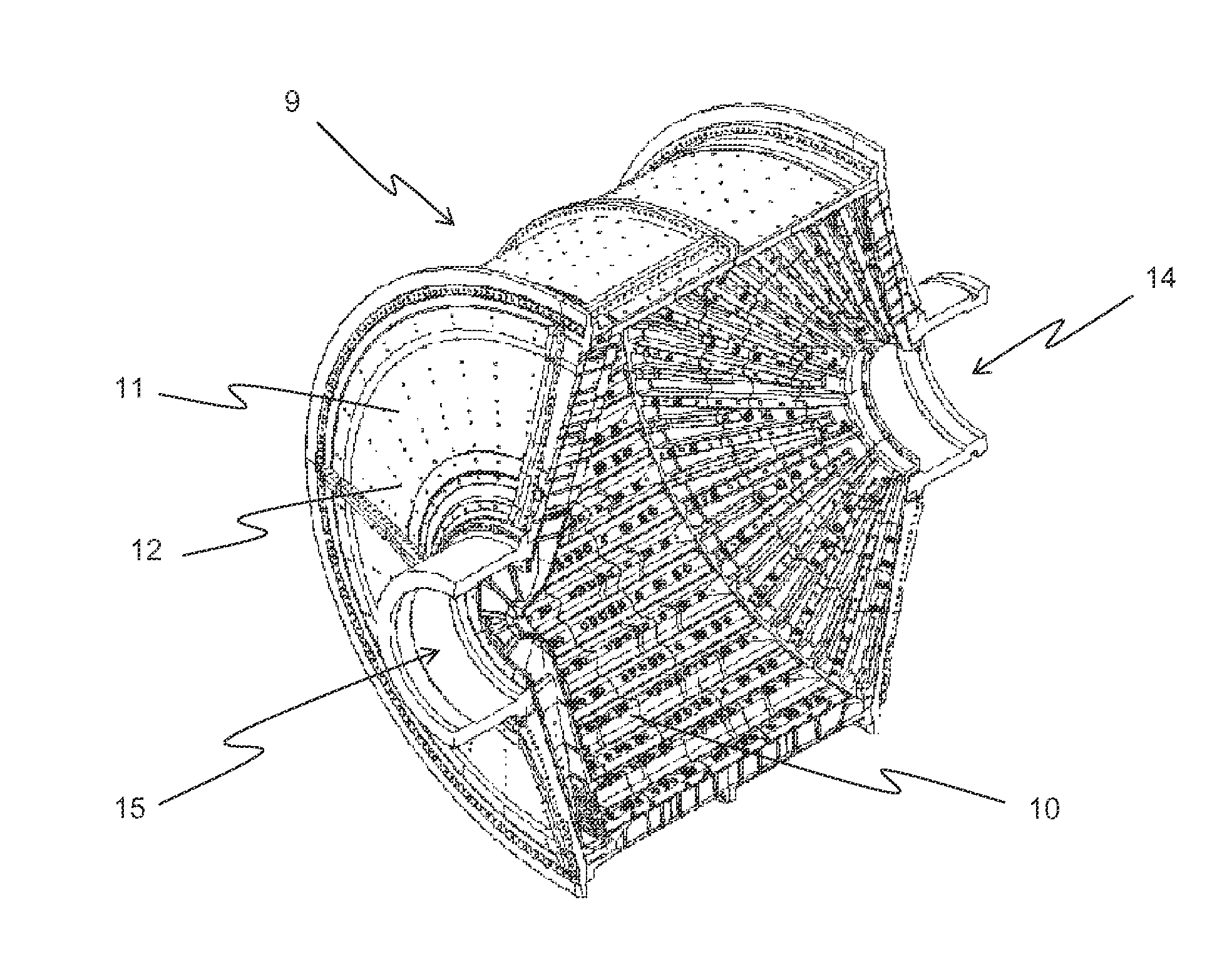
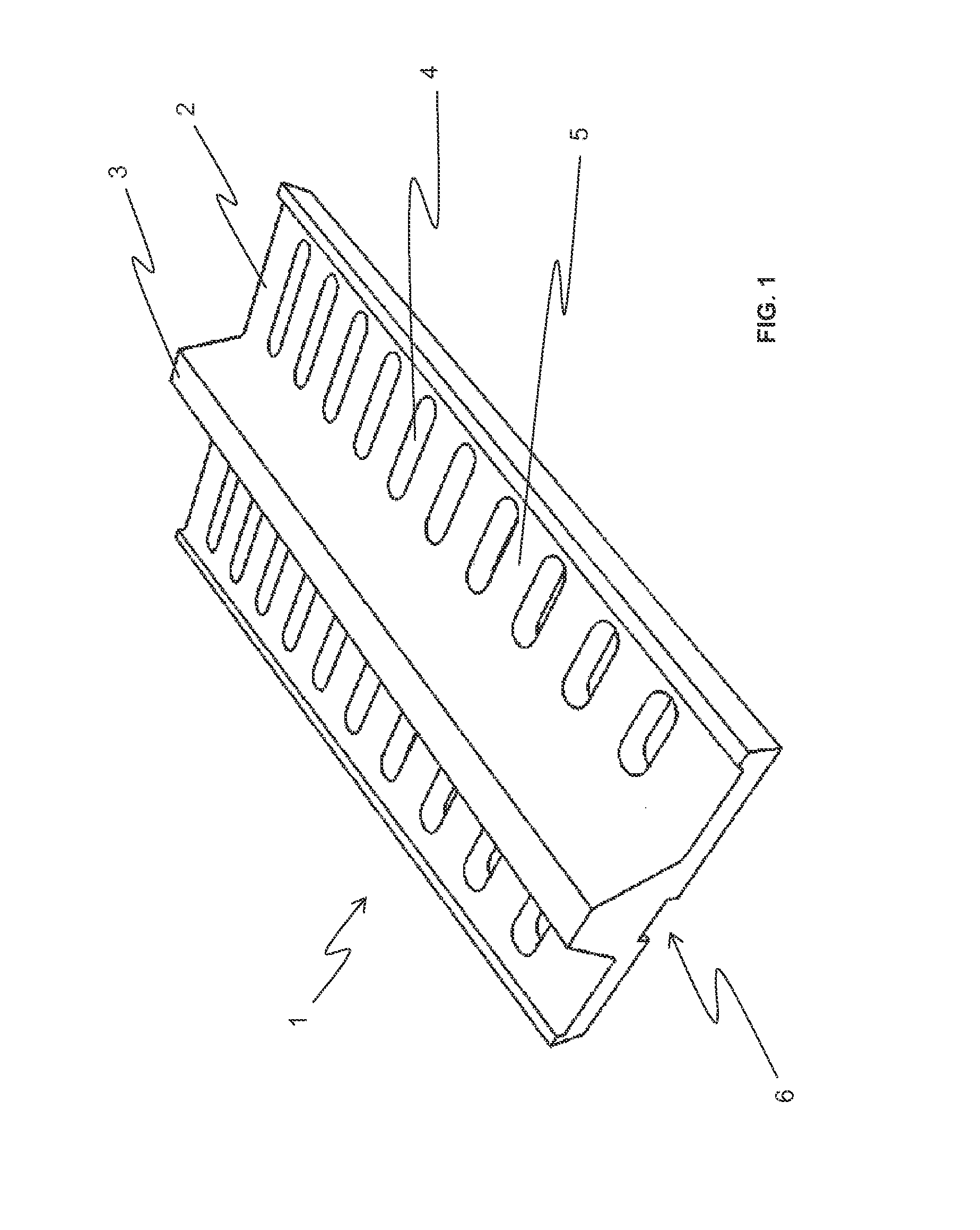
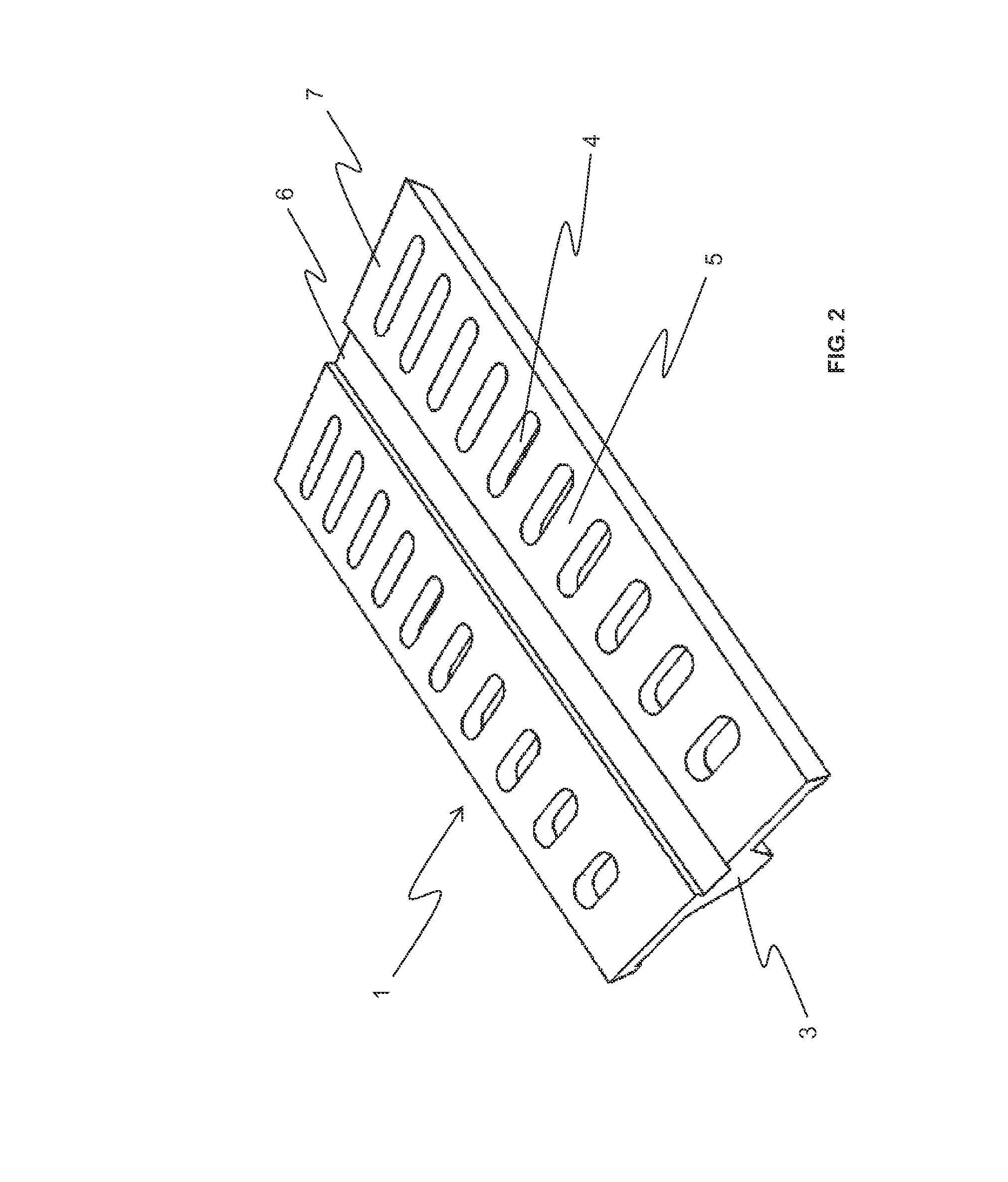
[0045]In the present invention as shown in FIG. 7, the signal from the accelerometer (16) is conveyed by wiring (23) located on the external surface (7) of the grate (1), wherein said wiring (23) reaches the trough (6) of the grate to then enter the chamber (15) of the supporting elements (22), wherein said wiring (23) connects the wireless transmitter (18) placed through a bolt (12) on the cover (11) of the mill (9), and wherein the wireless signal is output to the wireless receiver (20), where the signal is processed by a signal reader (21), usually a PC with a signal reader software. The wireless receiver (20) can be placed in a safe area outside the SAG mill at a distance of approximately 20 meters from the mill.

second embodiment

[0046]In the present invention as shown in FIG. 8, the signal from the accelerometer (16) is conveyed by wiring (23) located on the external surface (7) of the grate (1), wherein said wiring (23) reaches the trough (6) of the grate where the wireless transmitter (18) is placed, and wherein the wireless signal is output directly to the wireless receiver (20), where the signal is processed by a signal reader (21), usually a PC with a signal reader software. In this case, the wireless receiver (20) can also be placed in a safe area outside the SAG mill at a distance of approximately 20 meters from the mill.

[0047]In the second embodiment, the wireless signal from the transmitter (18) can be directly issued from the grate (1). While the second embodiment represents a rather simple embodiment of the invention to send the wireless signal, however said signal requires a greater number of field testing and testing inside the mill as to determine the correlation between the vibration received...


PUM


Abstract

A real-time monitoring system to monitor the wearing in the thickness of the ribs of a grate of a SAG mill. The grate can have a screening surface that includes a pulp lifter and an external surface that is not exposed to impacts, and can also include a central trough where the supporting elements fit and which allow securing the grate inside the mill through fitting bolts. The system can comprise: a sensor (accelerometer or strain gage) located on the external surface in which the sensor is connected to a sensor adaptor unit; a wireless transmitter connected to the sensor to transmit the signal from the sensor; a wireless receiver for receiving the signal from the wireless transmitter; and a signal reader connected to the wireless receiver which processes the signals received from the sensor.

Description

TECHNICAL FIELD OF THE INVENTION[0001]The present invention relates to a real time monitoring system for thickness of ribs, detecting undesired impacts on a grid, and obstructing the slots in grates of Semi-Autogenous mill (SAG), while the latter is in operation. The main feature in the system operation is the detection and analysis of the natural vibration frequency in the ribs of the grates and its relationship with the thickness of the ribs thereof, as well as the condition of rigidness generated when the slots are obstructed with the means of the grinding. The system mainly consists of: a vibration sensor; a module for wireless data transmission; and receiving module for that signal. As the vibration sensor is inserted in side the SAG mill to retrieve the measurements; such action results in the fact that the sensor should have certain features both in terms of frequency as in a maximum capacity to endure impacts. This system also allows detecting conditions of direct impact fro...

Claims


Application Information

Patent Timeline
IPC IPC(8): B02C17/18G01N29/12
CPCG01N29/12B02C17/1805B02C17/18B02C25/00B02C17/22
Inventor MAGNE, LUISTITICHOCA, GILDAALTAMIRANO, EDUARDOSEPULVEDA, GERMANVASQUEZ, MARCELO
Owner UNIV DE SANTIAGO DE CHILE
Features
  • Generate Ideas
  • Intellectual Property
  • Life Sciences
  • Materials
  • Tech Scout
  • Unparalleled Data Quality
  • Higher Quality Content
  • 60% Fewer Hallucinations
Learn More