Luminous keyboard

a keyboard and luminous technology, applied in the field of luminous keyboards, can solve the problem of relatively high manufacturing cost, and achieve the effect of reducing manufacturing time and cost, simplifying manufacturing steps, and reducing keyboard siz

Inactive Publication Date: 2014-06-05
CHANGSHU SUNREX TECH
View PDF10 Cites 54 Cited by
  • Summary
  • Abstract
  • Description
  • Claims
  • Application Information

AI Technical Summary

Benefits of technology

[0015]The effect of this invention resides in that a conductive lead is directly formed on one of the membrane circuit unit, the masking layer, and the reflector. Thus, a flexible substrate used in the conventional luminous keyboard can be omitted, thereby reducing size of the keyboard and simplifying manufacturing steps so as to reduce manufacturing time and costs.

Problems solved by technology

The manufacturing cost is relatively high due to the complex manufacturing process and the costly material.

Method used


Image

  • Luminous keyboard
  • Luminous keyboard
  • Luminous keyboard

Examples


Embodiment Construction

[0029]Before the present invention is described in greater detail, it should be noted herein that like elements are denoted by the same reference numerals throughout the disclosure.

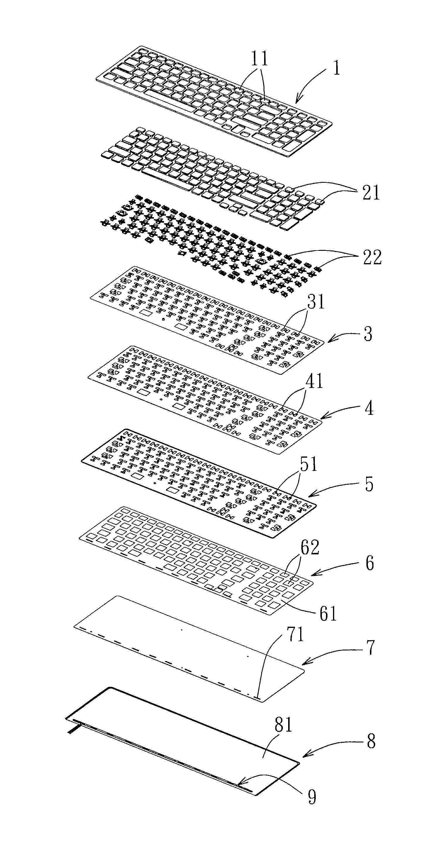
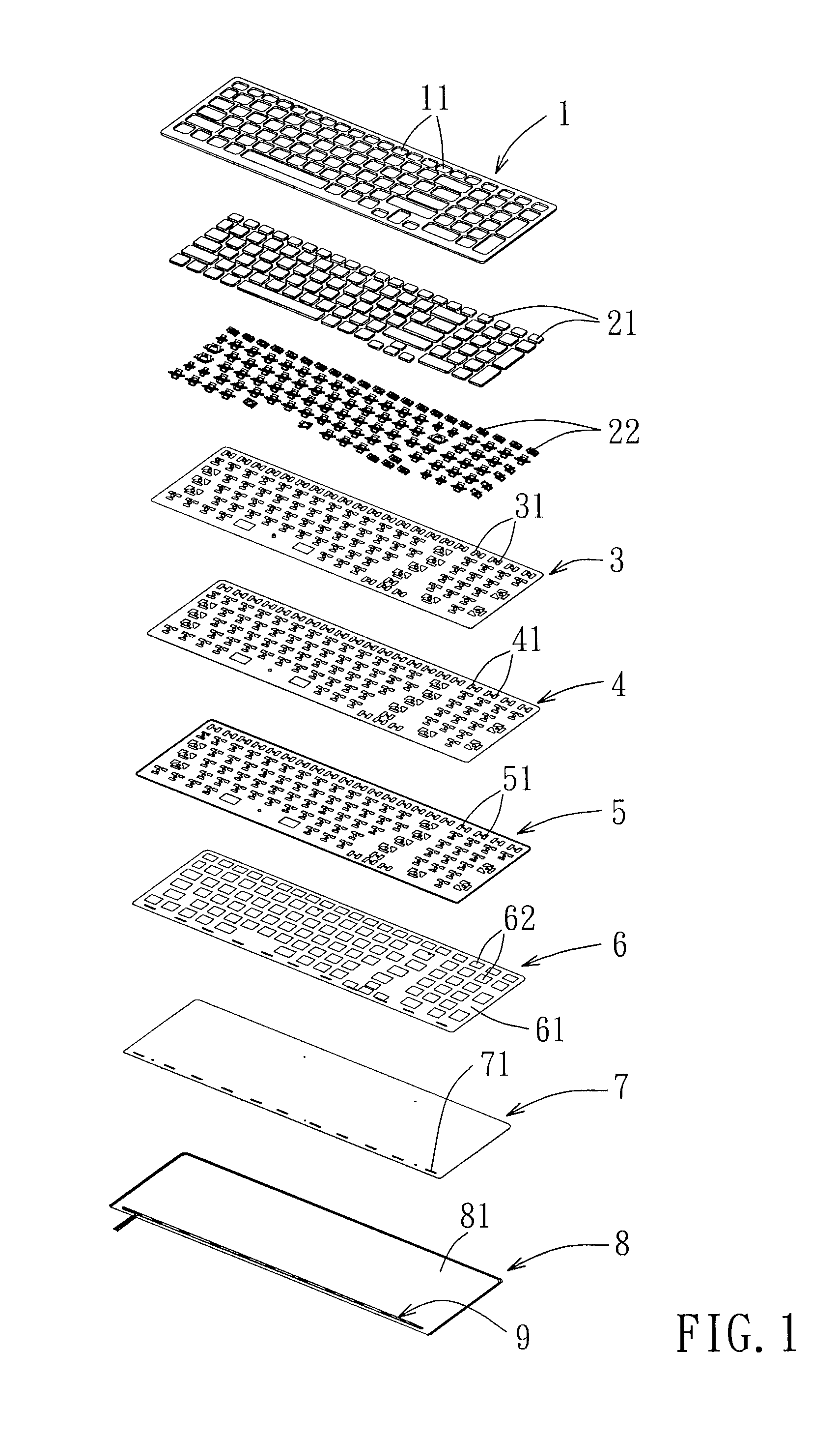
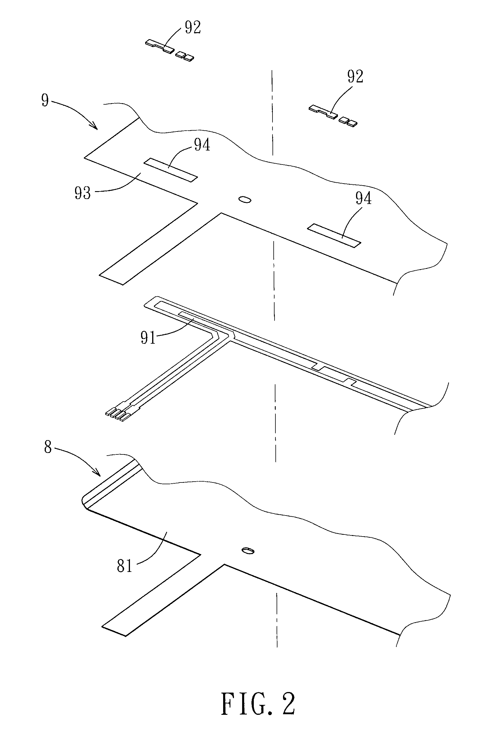
[0030]FIG. 1 illustrates a luminous keyboard in the first preferred embodiment according to this invention. The luminous keyboard comprises a frame 1, a plurality of key caps 21, a plurality of scissor linkages 22 and rubber domes (not shown) disposed under the key caps 21, a thin film 3 disposed under the scissor linkages 22 and the rubber domes, a membrane circuit unit 4 disposed under the thin film 3, and a base plate 5 disposed under the membrane circuit unit 4. Specifically, the frame 1 is formed with a plurality of openings 11 for passage of the key caps 21 such that the key caps 21 are exposed from the frame 1. The frame 1, the thin film 3, the membrane circuit unit 4, and the base plate 5 are bonded together by hot melting. When one of the key caps 21 is pressed, a respective one of the rubber dom...


PUM


Abstract

A luminous keyboard includes: a plurality of key caps; a light guiding plate disposed under the key caps; a reflector disposed under the light guiding plate; a masking layer disposed between the key caps and the light guiding plate; a membrane circuit unit disposed under the key caps and on the masking layer; and a luminous unit having a conductive lead, and an illuminant electrically connected to the conductive lead. The conductive lead is made of a material including a conductive polymer gel and a conductive powder and is formed directly on one of the reflector, the masking layer and the membrane circuit unit.

Description

BACKGROUND OF THE INVENTION[0001]1. Field of the Invention[0002]This invention relates to a luminous keyboard, more particularly to a luminous keyboard having backlight functionality.[0003]2. Description of the Related Art[0004]A conventional luminous keyboard comprises: a press key module and a backlight module including a luminous unit and disposed under the press key module.[0005]The luminous unit is generally formed on a flexible substrate by consecutive steps of copper plating, layer forming, developing and etching. The manufacturing cost is relatively high due to the complex manufacturing process and the costly material.[0006]On the other hand, since the flexible substrate is stacked with other components of the backlight module, e.g., a masking layer, a light guiding plate (LGP), a reflector and so on, the conventional luminous keyboard has a relatively thick structure.SUMMARY OF THE INVENTION[0007]Therefore, an object of the present invention is to provide a luminous keyboar...

Claims


Application Information

Patent Timeline
Patent Type & Authority Applications(United States)
IPC IPC(8): H01H13/702
CPCH01H13/702H01H3/125H01H13/83H01H2219/044H01H2219/06H01H2219/062H01H2229/026
Inventor ZHANG, QING
Owner CHANGSHU SUNREX TECH
Why Eureka
Try Eureka