Hammer for shredding machines

a technology of shredding machine and hammer, which is applied in the field of industrial shredding systems, can solve the problems of affecting the shredding effect of the hammer, the material of the hammer tends to wear away, and the shredding is routinely exposed to extremely harsh conditions of use, so as to improve the shredding effect of the material, improve the shredding effect, and improve the effect of shredding

Inactive Publication Date: 2014-06-05
ESCO GRP LLC
View PDF13 Cites 9 Cited by
  • Summary
  • Abstract
  • Description
  • Claims
  • Application Information

AI Technical Summary

Benefits of technology

[0015]In another aspect of the invention, the centers of mass of the leading region and of the trailing region are defined within the angle between the leading axis and the trailing axis. Such a configuration provides an effective coordination of wear edge length and working portion mass to improve shredding of the material in the shredding chamber.
[0016]In another aspect of the invention, a shredding machine includes one or more hammers with one or more of the above-noted inventive features. Such a machine provides a shredding process that produces increased throughput of the target material. It is further believed that the process provides greater reduction of the target material for easy and better downstream processing of the target material.

Problems solved by technology

Shredder hammers are therefore routinely exposed to extremely harsh conditions of use, and so typically are constructed from hardened steel materials, such as low alloy steel or high manganese alloy content steel (such as Hadfield Manganese Steel).
In particular, as the shredder hammer blade or impact area undergoes repeated collisions with the material to be processed, the material of the shredder hammer tends to wear away.

Method used


Image

  • Hammer for shredding machines
  • Hammer for shredding machines
  • Hammer for shredding machines

Examples


Embodiment Construction

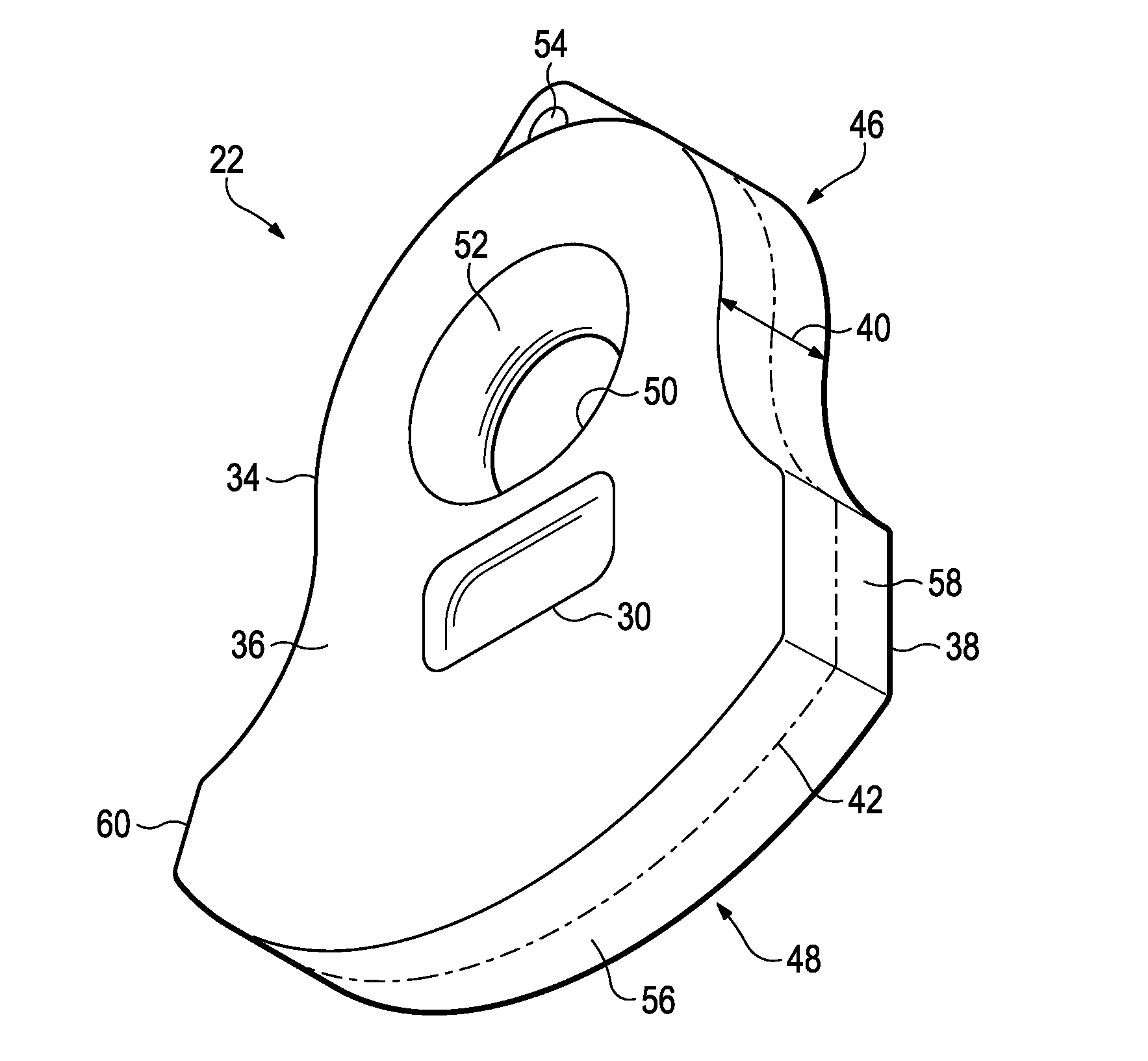
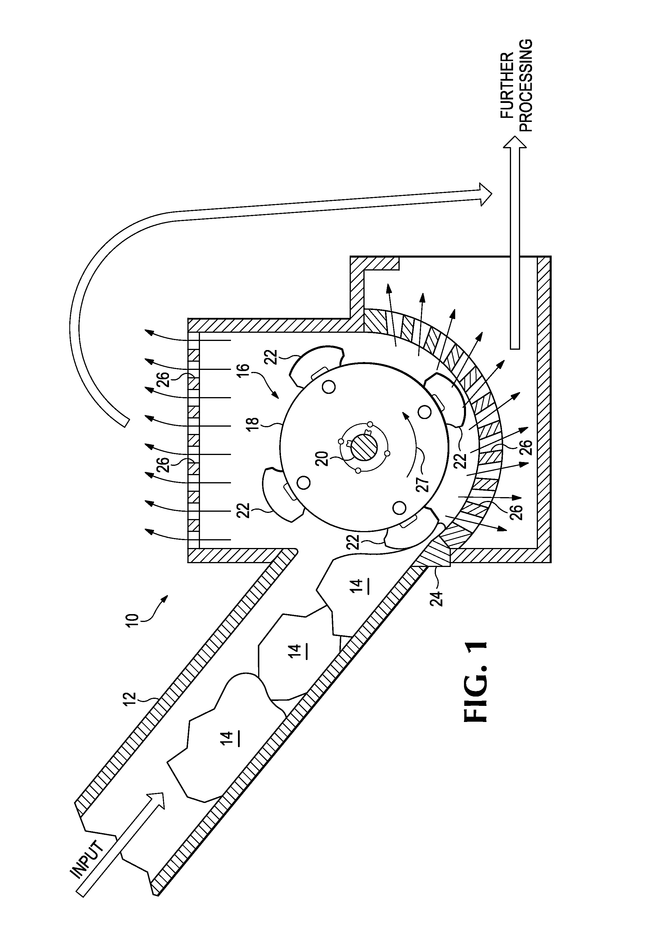
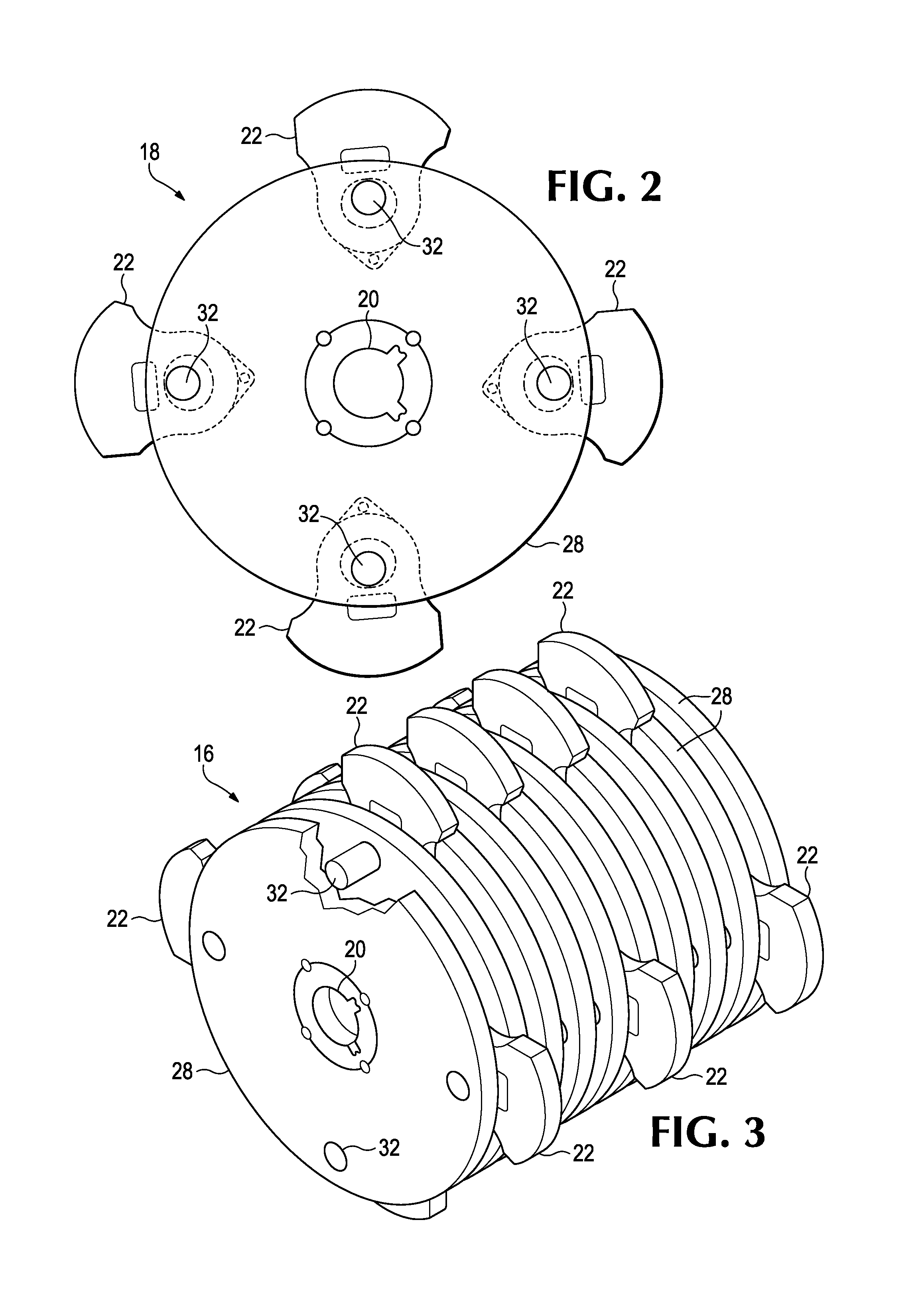
[0043]Hammers in reduction systems operate at very high speeds to impact and separate materials into smaller portions allowing them to be further processed in downstream operations. The hammers are mounted to a head and are rotated inside a housing. The target material is initially impacted by a leading impact face of the hammer passing an anvil or cutter bar near the material inlet. Contact of the hammers with the material fed into the shredding machine fractures, compresses and shears the material into smaller pieces. The target material is reduced in size as the materials are compressed and shredded between the outer surface (i.e., the wear edge) of the hammer and the grates forming a portion of the walls of the reducing system. These grates define openings that allow the material to exit when small enough to pass through the grate openings.

[0044]With no material in the housing of the system, the head with the hammers rotates at operating speeds. The hammers are typically free to...


PUM


Abstract

Shredder hammers having first and second major surfaces on opposing sides, and a circumferential edge. A mounting portion includes a mounting hole that extends from the first major surface to the second major surface, and is configured to receive a hammer mounting pin for mounting in a reducing system. The circumferential edge includes a primary impact face to initially impact materials to be reduced and a wear edge to subsequently crush and shear the material against a wall of the equipment. The hammer is biased forward on the pin to admit more material to be crushed between the wear edge and the grates.

Description

RELATED APPLICATION[0001]This application claims priority benefits to U.S. Provisional Patent Application No. 61 / 649,019 filed May 18, 2012 and entitled “Asymmetrical Impact Hammers,” which is incorporated herein by reference in its entirety.FIELD OF THE INVENTION[0002]The present invention relates to industrial shredding systems. More particularly, this invention relates to shredding systems that include shredder hammers.BACKGROUND OF THE INVENTION[0003]Industrial shredding equipment typically is used to break large objects into smaller pieces that can be more readily processed, for example as in the recycling industry. Commercially available shredders range in size from those that shred materials like rubber (e.g., car tires), wood, and paper to larger shredding systems that are capable of shredding scrap metal, automobiles, automobile body parts, and the like.[0004]The core of most industrial shredding systems is the shredding chamber, where multiple shredder hammers are spun on ...

Claims


Application Information

Patent Timeline
Patent Type & Authority Applications(United States)
IPC IPC(8): B02C13/28
CPCB02C13/28B02C13/04B02C13/284B02C2013/2808B02C2013/28609B02C2013/28672
Inventor GRAF, DAVID M.WEEKS, MICHAEL R.HOICE, JOHN P.MORROW, DANIEL R.BRISCOE, TERRY L.CARPENTER, CHRISTOPHER M.
Owner ESCO GRP LLC
Why Eureka
Try Eureka