Multi-primary color display device
a display device and primary color technology, applied in the field of display devices, can solve the problem of narrow color reproduction range (referred to as the “color reproduction range”), and achieve the effect of reducing the size of sub pixels
- Summary
- Abstract
- Description
- Claims
- Application Information
AI Technical Summary
Benefits of technology
Problems solved by technology
Method used
Image
Examples
example 1
4 Primary Colors, 4 Sub Pixels, 2 Virtual Pixels
[0172]FIG. 29 shows a pixel structure in Example 1. In the example shown in FIG. 29, each pixel P is formed of four sub pixels, specifically, a red sub pixel R, a green sub pixel G, a blue sub pixel B, and a yellow sub pixel Ye. In each pixel P, these sub pixels are located in the order of the blue sub pixel B, the green sub pixel G, the red sub pixel R and the yellow sub pixel Ye from left to right in the row direction. The first virtual pixel VP1 is formed of the blue sub pixel B, the green sub pixel G and the red sub pixel R, and the second virtual pixel VP2 is formed of the red sub pixel R, the yellow sub pixel Ye and the blue sub pixel B. In this case, the sub pixel shared by the first virtual pixel VP1 and the second virtual pixel VP2 is the red sub pixel R or the blue sub pixel B. Therefore, a red or blue false color may be generated.
[0173]The detection of the n-pixel width line (namely, detection of an area in which a false col...
example 2
4 Primary Colors; 4 Sub Pixels; 2 Virtual Pixels
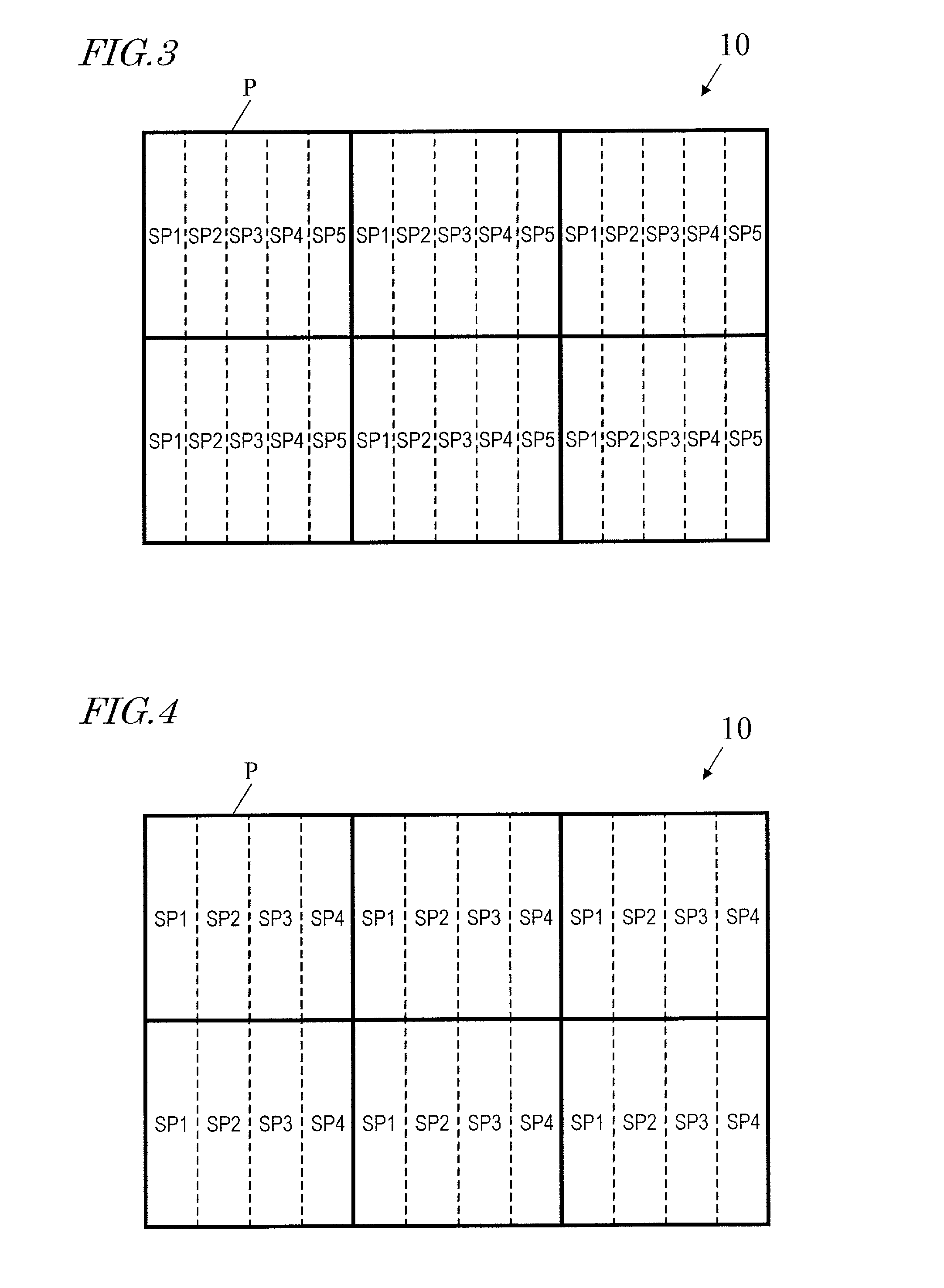
[0185]FIG. 32 shows a pixel structure in Example 2. In the example shown in FIG. 32, each pixel P is formed of four sub pixels, specifically, a red sub pixel R, a green sub pixel G, a blue sub pixel B, and a cyan sub pixel C. In each pixel P, these sub pixels are located in the order of the blue sub pixel B, the green sub pixel G, the red sub pixel R and the cyan sub pixel C from left to right in the row direction. The first virtual pixel VP1 is formed of the blue sub pixel B, the green sub pixel G and the red sub pixel R, and the second virtual pixel VP2 is formed of the red sub pixel R, the cyan sub pixel C and the blue sub pixel B. In this case, the sub pixel shared by the first virtual pixel VP1 and the second virtual pixel VP2 is the red sub pixel R or the blue sub pixel B. Therefore, a red or blue false color may be generated.
[0186]FIG. 33 shows a filter response r when a [−1 1 1 −1] filter is used as a filter for detecting a 2-p...
example 3
5 Primary Colors; 5 Sub Pixels; 2 Virtual Pixels
[0192]FIG. 35 shows a pixel structure in Example 3. In the example shown in FIG. 35, each pixel P is formed of five sub pixels, specifically, a red sub pixel R, a green sub pixel G, a blue sub pixel B, a cyan sub pixel C, and a yellow sub pixel Ye. In each pixel P, these sub pixels are located in the order of the blue sub pixel B, the yellow sub pixel Ye, the red sub pixel R, the cyan sub pixel C and the green sub pixel G from left to right in the row direction. The first virtual pixel VP1 is formed of the blue sub pixel B, the yellow sub pixel Ye and the red sub pixel R, and the second virtual pixel VP2 is formed of the red sub pixel R, the cyan sub pixel C, the green sub pixel G and the blue sub pixel B. In this case, the sub pixel shared by the first virtual pixel VP1 and the second virtual pixel VP2 is the red sub pixel R or the blue sub pixel B. Therefore, a red or blue false color may be generated.
[0193]FIG. 36 shows a filter res...
PUM
 Abstract
Description
Claims
Application Information
 - R&D
- Intellectual Property
- Life Sciences
- Materials
- Tech Scout
- Unparalleled Data Quality
- Higher Quality Content
- 60% Fewer Hallucinations
Browse by: Latest US Patents, China's latest patents, Technical Efficacy Thesaurus, Application Domain, Technology Topic, Popular Technical Reports.
© 2025 PatSnap. All rights reserved.Legal|Privacy policy|Modern Slavery Act Transparency Statement|Sitemap|About US| Contact US: help@patsnap.com


