Metal core printed circuit board as heat sink for leds

a printed circuit board and led technology, applied in the field of applications, can solve the problems of self-destruction of devices, overheating of junctions, etc., and achieve the effects of good thermo-conductor, good ventilation, and large aluminum surface area

Inactive Publication Date: 2014-06-05
OPI PRODUCTS
View PDF0 Cites 13 Cited by
  • Summary
  • Abstract
  • Description
  • Claims
  • Application Information

AI Technical Summary

Benefits of technology

[0003]According to the invention, power LEDs are implanted in a specially designed printed circuit board (PCB) that is known in the art as a Metal Core Printed Circuit Board (MCPCB). A regular PCB is one layer or multiple layers of thin copper on an insulating substrate such as fiber glass. By way of contrast, a MCPCB has a regular copper layer that is used for the traces and soldering pads, a very thin special insulating material which is a very good thermo-conductor, and a layer of aluminum. By using a MCPCB, heat from a device such as an LED is transferred through the insulating layer to the aluminum where, given the special thermo-conductive properties of the aluminum, the heat spreads and is dissipated. The larger the aluminum surface area, the better the ventilation (air movement), and the lower the ambient temperature the better the cooling effect. Although MCPCBs are well known, the invention, based on studies which show the effect of bending of the MCPCB under different bending angles, uses an MCPCB which is bended over a radius that is not smaller than a determined value (depending of the overall thickness of the MCPCB) without any negative effects on the insulating layer and copper traces in the area of bending. When bent in this manner, it is possible to at least double the surface area of the heat sink used in an LED nail care heating appliance. By bending an MCPCB with installed LEDs to follow the natural curvature (based on the shape of a human hand) of the appliance housing, the need for additional heat sinks or fans to control the heat generated by the LEDs is eliminated. In this manner, which is a very simple and economic solution, the heat dissipation surface is increased. Tests show that under identical ambient conditions (room temperature and air flow) there is a difference of 5-6 degree Celsius between the temperature measured on a regular straight surface that fits in a particular housing and one that has the added surface area gained through the bending of the MCPCB.

Problems solved by technology

However, use of LEDs in such an environment creates a critical issue which must be dealt with, namely thermal management.
If the heat is not guided away, the junction will overheat which translates first in a drop of light output of the LED and later on self-destruction of the device.

Method used


Image

  • Metal core printed circuit board as heat sink for leds
  • Metal core printed circuit board as heat sink for leds
  • Metal core printed circuit board as heat sink for leds

Examples


Embodiment Construction

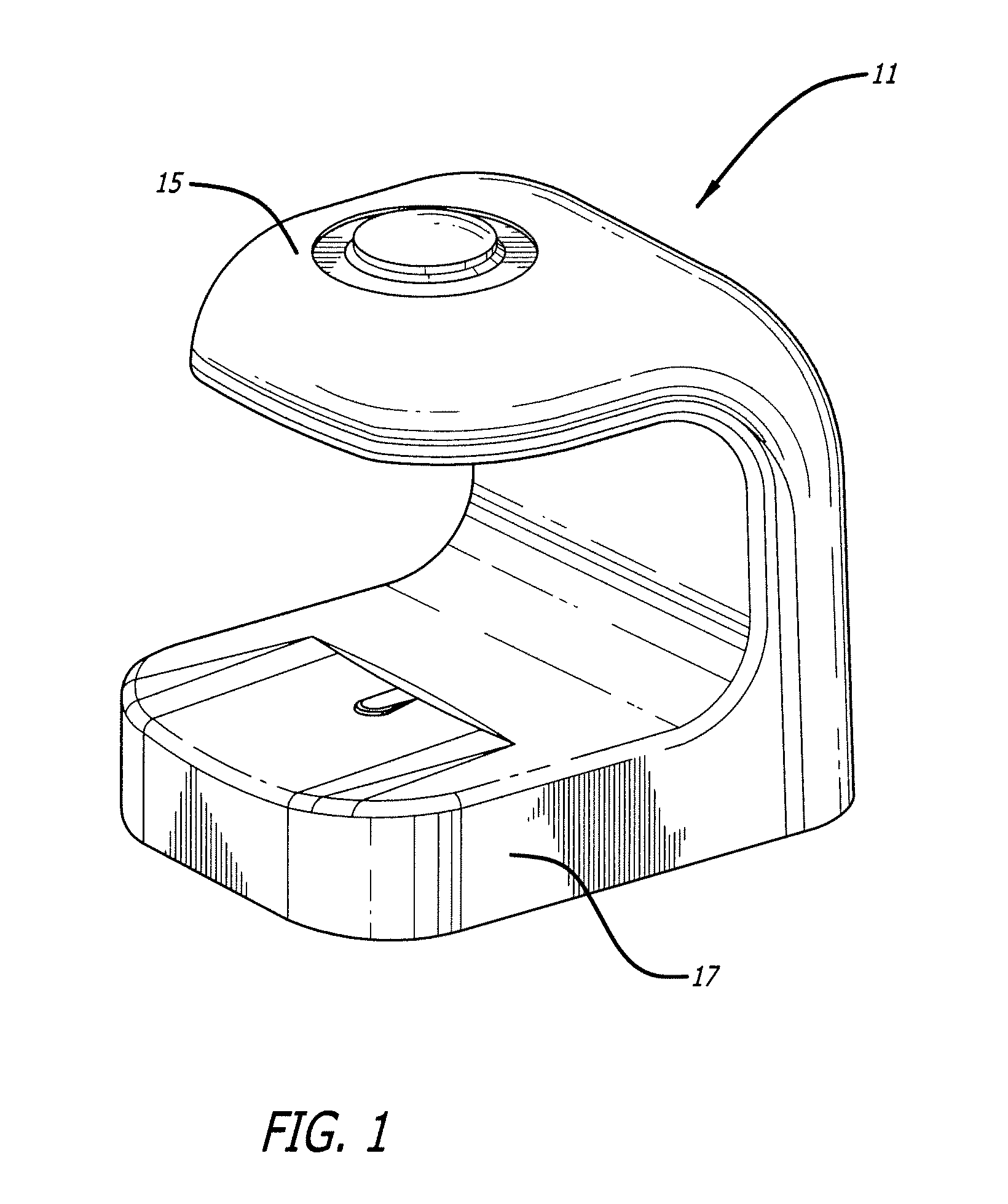
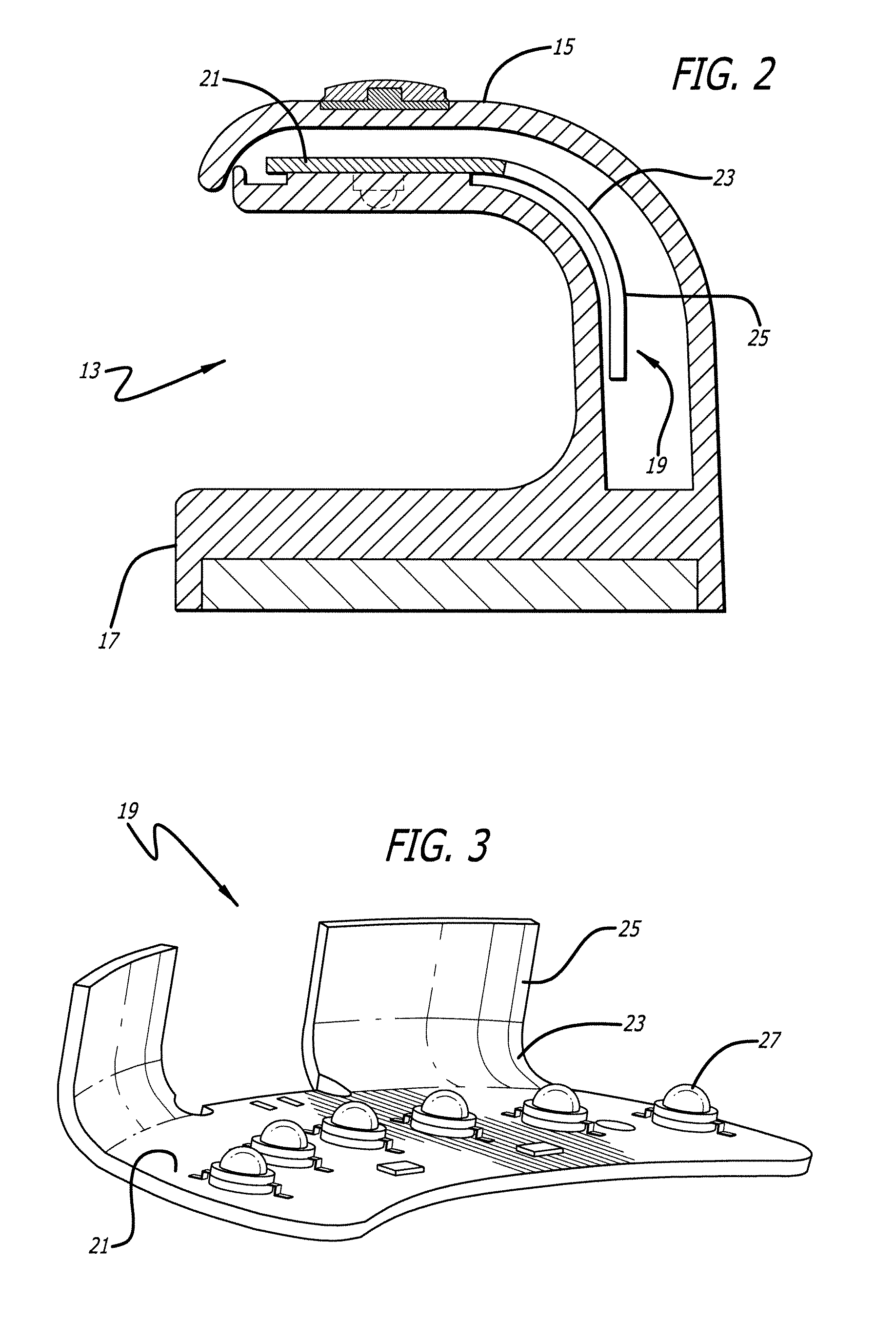
[0011]Referring first to FIG. 1, the invented fingernail drying apparatus 11 is shown having a top portion 15 and base 17. FIG. 2 shows the invented fingernail drying apparatus in a partial cutaway, side view including an opening 13 into which a hand with fingernails coated with nail polish or the like to be dried is inserted. Located within the top portion is a metal core printed circuit board 19 which is described in further detail in FIGS. 3-6. Although not shown in FIG. 2, board 19 has a set of LEDs facing downward from top 15 towards base 17.

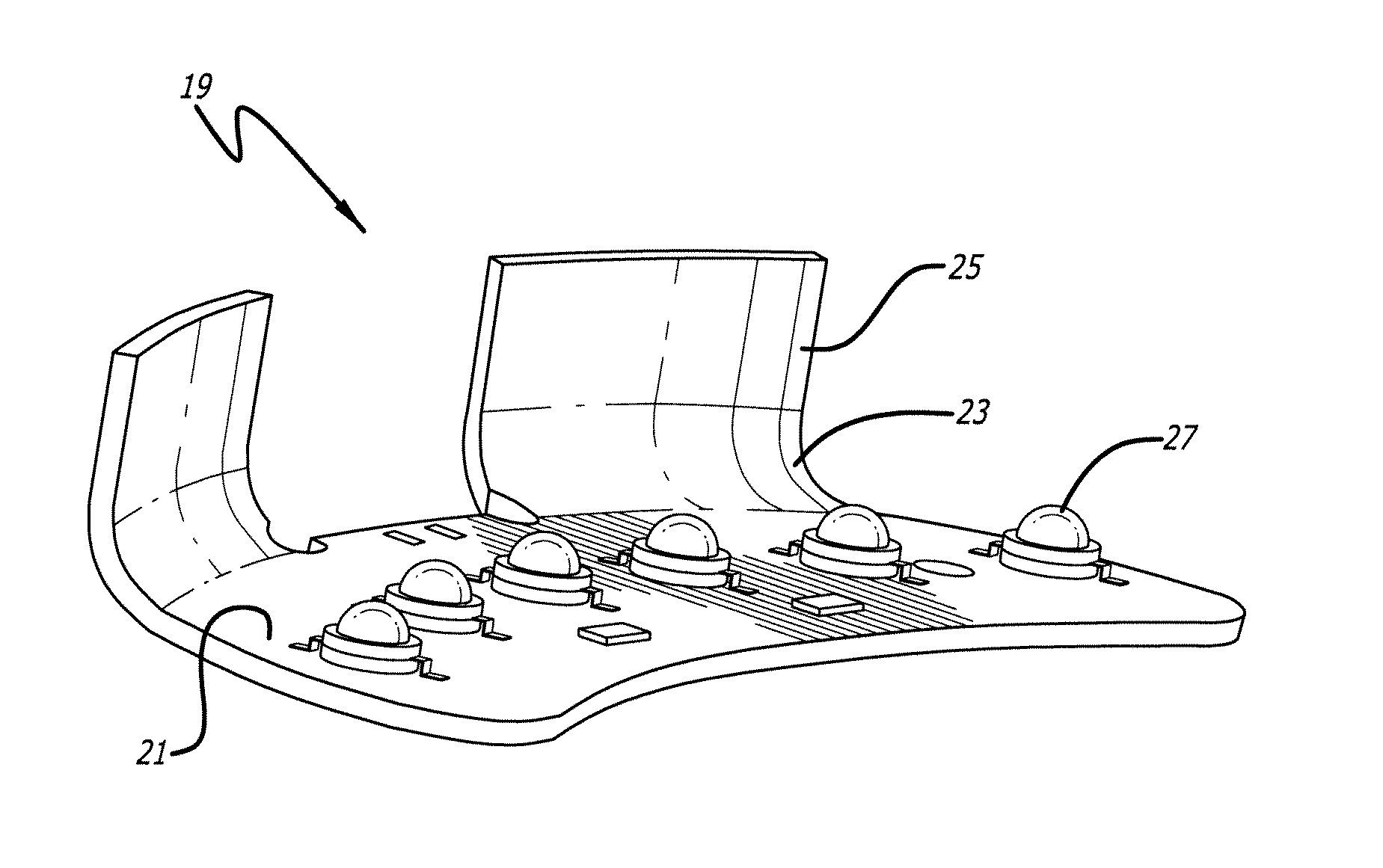
[0012]FIG. 3 shows the invented MCPCB 19 having a base 21, rounded corners 23 and extensions 25 from the rounded corners. Installed on base 21 is a set of LEDs 27. FIGS. 4-7 are top plan, side, front elevation and rear perspective views of board 19, respectively which are provided to clearly show the relationship between the mounted LEDs 27, rounded corners 23 and extended portions 25.

[0013]By providing MCPCB 19 with the rounded corners 23 ...


PUM


Abstract

Power LEDs are implanted in a specially designed printed circuit board (PCB) that is known in the art as a Metal Core Printed Circuit Board (MCPCB). The MCPCB is bended over to so as to have rounded corners having a radius that is not smaller than a determined value depending of the overall thickness of the MCPCB and other factors without any negative effects on the insulating layer and copper traces in the area of bending. In this manner, the surface area of the heat sink used in an LED nail care curing appliance is increased. The MCPCB with installed LEDs with rounded corners thereby follows the natural curvature (based on the shape of a human hand) of the appliance housing, eliminating the need for additional heat sinks or fans to reduce the heat generated by the LEDs.

Description

FIELD OF THE INVENTION[0001]The invention is directed to the field of appliances used by nail care professionals to cure nail gel or other coating applied to the fingernails. The invention is specifically directly to the use of LEDs as a source of ultra-violet radiation for such curing.BACKGROUND OF THE INVENTION[0002]Although normally used as a light source, ultra-violet emitting Light Emitting Diodes (LEDs) emit ultra-violet (UV) radiation e.g., 400 nm. which can be used in applications where such radiation is a desired property. For example, in the nail care field, LEDs known as power LEDs can be placed in a housing shaped to receive the fingers of a human hand so that when nail gel or other nail coating is applied, by inserting the fingers into the housing, the UV radiation is used to cure the coating which operates to solidify the gel, changing it from a fluid state to a solid state. However, use of LEDs in such an environment creates a critical issue which must be dealt with, ...

Claims


Application Information

Patent Timeline
Patent Type & Authority Applications(United States)
IPC IPC(8): F21V29/00
CPCF21V29/004A45D29/00H05K1/0203H05K1/0284H05K1/05H05K2201/10106F21V29/70A61Q3/00F26B3/28
Inventor HORVATH, GAVRIL
Owner OPI PRODUCTS
Why Eureka
Try Eureka