Multilayer tube in ceramic matrix composite material, resulting nuclear fuel cladding and associated manufacturing processes

a ceramic matrix composite material and multi-layer tube technology, applied in the direction of reactor fuel elements, lamination, applications, etc., can solve the problems of not being adapted for use as pressure chambers or pressurized conduits, material hermetic over the entire range of potential operation, etc., to achieve good heat conductivity, small temperature difference between sides, and high porosity

Active Publication Date: 2014-06-05
COMMISSARIAT A LENERGIE ATOMIQUE ET AUX ENERGIES ALTERNATIVES
View PDF5 Cites 32 Cited by
  • Summary
  • Abstract
  • Description
  • Claims
  • Application Information

AI Technical Summary

Benefits of technology

[0030]As previously explained, CMC materials only have a hermetic seal over a very small range which corresponds to the range of linear elasticity of the CMC material under consideration, since beyond this elasticity limit they undergo multi-cracking. The particular arrangement of the layers of the multilayer tubular part according to the invention allows the hermetic sealing of the part to be maintained up to the break point of the CMC materials rather than solely within their elastic range.
[0084]by facilitating the hermetic sealing of the part at its open ends.

Problems solved by technology

Despite their numerous advantages, CMC materials have one major disadvantage however: they are not hermetic over their entire range of potential operation.
Therefore, these materials are not adapted for applications as pressure chamber or pressurized conduit as is the case in particular for nuclear fuel claddings or heat exchanger tubes since they do not offer any guarantee of leak-tightness over their entire potential range of operation.
For example, for a nuclear reactor fuel element whose cladding forms the first containment barrier for radioactive products generated when in operation, the risk of lack of hermetic tightness before dismantling clearly amounts to a major drawback making CMC materials in theory unsuitable for such use and unacceptable for nuclear safety authorities.
If the values mentioned above (on the basis of FIG. 1) are compared with the operating conditions usually required for nuclear fuel cladding, for example elongations of 0.2 to 0.5% and stresses higher than 100 MPa possibly reaching 200 MPa under the most extreme sizing conditions, it then becomes evident that a CMC cladding alone is not able to meet the requirement of tightness that is strictly laid down by safety regulations.
However, aside from the fact that the obtaining of a monolithic ceramic layer over the usual lengths of a nuclear fuel cladding (greater than 1 metre and possibly reaching 4 metres) is particularly difficult (document [2] effectively mentions the producing of sections that then have to be assembled, which carries the risk of weakening the final component), the hermetic sealing of the claddings described in documents [1] to [3] is only valid within the linear elasticity range of the multilayer formed, and in particular within the elasticity range of the ceramic used, which is unfortunately much reduced.
Namely, this means that if a crack is initiated within the multilayer and more particularly in the monolithic ceramic ensuring the hermetic seal (after mechanical shock or damage beyond its linear elastic strength) the hermetic seal is lost and the cladding becomes permeable.
In fact despite its ultimate strength performance, the multilayer proposed in document [2] is not capable of meeting the specifications for a nuclear fuel element, which require the hermetic seal of the cladding to be guaranteed over the entire operating range which clearly extends beyond 0.2% strain.
Therefore, the application of this solution to nuclear fuels (which to our knowledge has never yet been implemented) would require the use of large thicknesses for the metal layer, which would considerably limit the choice of metal material (on account of neutron absorption of refractory metals).

Method used


Image

  • Multilayer tube in ceramic matrix composite material, resulting nuclear fuel cladding and associated manufacturing processes
  • Multilayer tube in ceramic matrix composite material, resulting nuclear fuel cladding and associated manufacturing processes
  • Multilayer tube in ceramic matrix composite material, resulting nuclear fuel cladding and associated manufacturing processes

Examples


Embodiment Construction

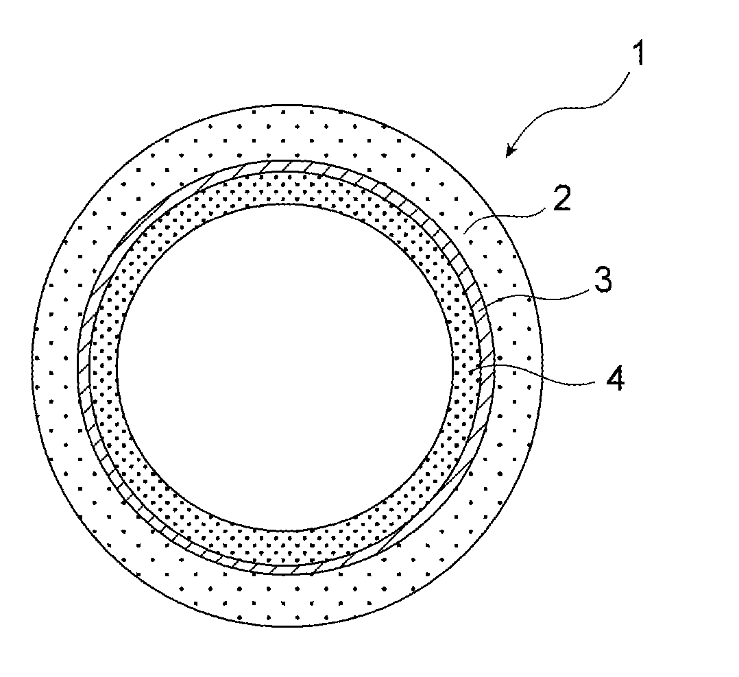
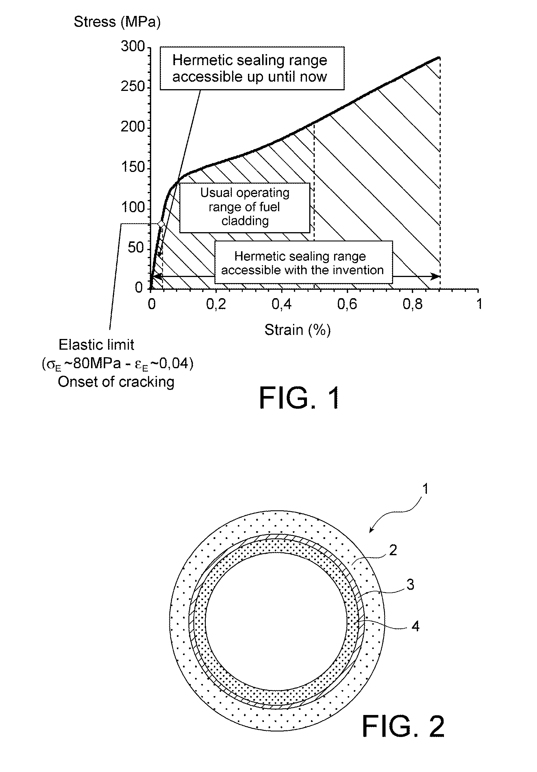
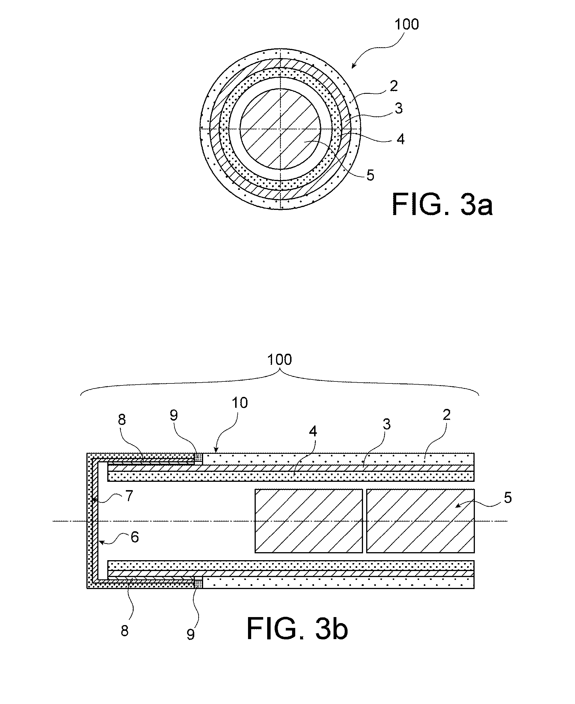
[0018]This objective is reached by the invention which firstly proposes a multilayer tubular part comprising a metal layer forming a metal tubular body and two layers in ceramic matrix composite material covering the metal tubular body, characterized in that one of the two layers in ceramic matrix composite material coats the inner surface of the metal tubular body to form an inner tubular body, whilst the other of the two layers in ceramic matrix composite material coats the outer surface of the metal tubular body to form an outer tubular body, the metal tubular body therefore being sandwiched between the inner and outer tubular bodies, the metal tubular body having a mean thickness narrower than the mean thicknesses of the inner and outer tubular bodies.

[0019]The metal tubular body may be in metal or in a metal alloy.

[0020]It is specified that in the foregoing and in the remainder hereof that a ceramic matrix composite material is a material with fibre reinforcement.

[0021]The cros...


PUM

PropertyMeasurementUnit
thicknessaaaaaaaaaa
thicknessaaaaaaaaaa
temperatureaaaaaaaaaa

Abstract

The invention relates to a multilayer tubular part (1) comprising a metal layer forming a metal tubular body (3) and two layers in ceramic matrix composite material covering the metal tubular body, wherein one of the two layers in ceramic matrix composite material covers the inner surface of the metal tubular body to form an inner tubular body (4), whilst the other of the two layers in ceramic matrix composite material covers the outer surface of the metal tubular body to form an outer tubular body (2), the metal tubular body therefore being sandwiched between the inner and outer tubular bodies. The metal tubular body is in metal or metal alloy. Finally, the metal tubular body has a mean thickness smaller than the mean thicknesses of the inner and outer tubular bodies. A said part is useful in particular for producing nuclear fuel claddings.

Description

TECHNICAL FIELD[0001]The present invention relates to the field of parts in ceramic matrix composite material. In particular, the present invention relates to the field of fuel elements for nuclear reactors, and more particularly to an improved cladding for nuclear fuel, to nuclear reactor fuel rods using such claddings and the manufacturing processes thereof.[0002]Said improved fuel cladding may, as an example, be used to produce fuel elements of pin or rod geometry in fourth generation reactors of GFR type (Gas-cooled fast reactor).[0003]It can also be used in other nuclear reactors such as PWRs (pressurized water reactors), BWRs (boiling water reactors) or SFRs (sodium-cooled fast reactors).STATE OF THE PRIOR ART[0004]Ceramic matrix composite materials (CMCs) are particularly appreciated in numerous fields on account of their low density, remarkable mechanical properties in particular in terms of hardness, toughness, resistance to wear and resistance to mechanical and heat shock,...

Claims


Application Information

Patent Timeline
Patent Type & Authority Applications(United States)
IPC IPC(8): G21C3/07G21C3/06
CPCB32B1/08B32B9/005B32B9/041B32B2307/538B32B2307/54B32B2597/00C04B37/021C04B37/025C04B2235/6028C04B2235/6562C04B2235/963C04B2237/086C04B2237/36C04B2237/365C04B2237/38C04B2237/385C04B2237/403C04B2237/704C04B2237/706C04B2237/765C04B2237/84G21C3/07G21C3/10G21C21/02Y02E30/30G21C3/06
Inventor ZABIEGO, MAXIMESAUDER, CEDRICLORRETTE, CHRISTOPHEGUEDENEY, PHILIPPE
Owner COMMISSARIAT A LENERGIE ATOMIQUE ET AUX ENERGIES ALTERNATIVES
Why Eureka
Try Eureka