Cage for a toroidal roller bearing

Active Publication Date: 2014-06-05
AB SKF
View PDF24 Cites 1 Cited by
  • Summary
  • Abstract
  • Description
  • Claims
  • Application Information

AI Technical Summary

Benefits of technology

[0021]The method has the advantage that it will facilitate assembling and dismounting of the bearing. It will reduce the risk of roller elements falling out from the bearing after the roller elements have been properly inserted into the bearing. By rotating the inner ring and the cage relative the outer ring during assembling or dismounting, more roller pockets will be at the location where the portion is axially outside the inner ring of the bearing, and thus more roller elements may be inserted or pulled out. For some bea

Problems solved by technology

One drawback with this cage design is that it makes it difficult to assemble wider and larger toroidal roller bearings.
For

Method used


Image

  • Cage for a toroidal roller bearing
  • Cage for a toroidal roller bearing
  • Cage for a toroidal roller bearing

Examples


Embodiment Construction

[0032]Below, the invention will now be further explained with support from the accompanying drawings.

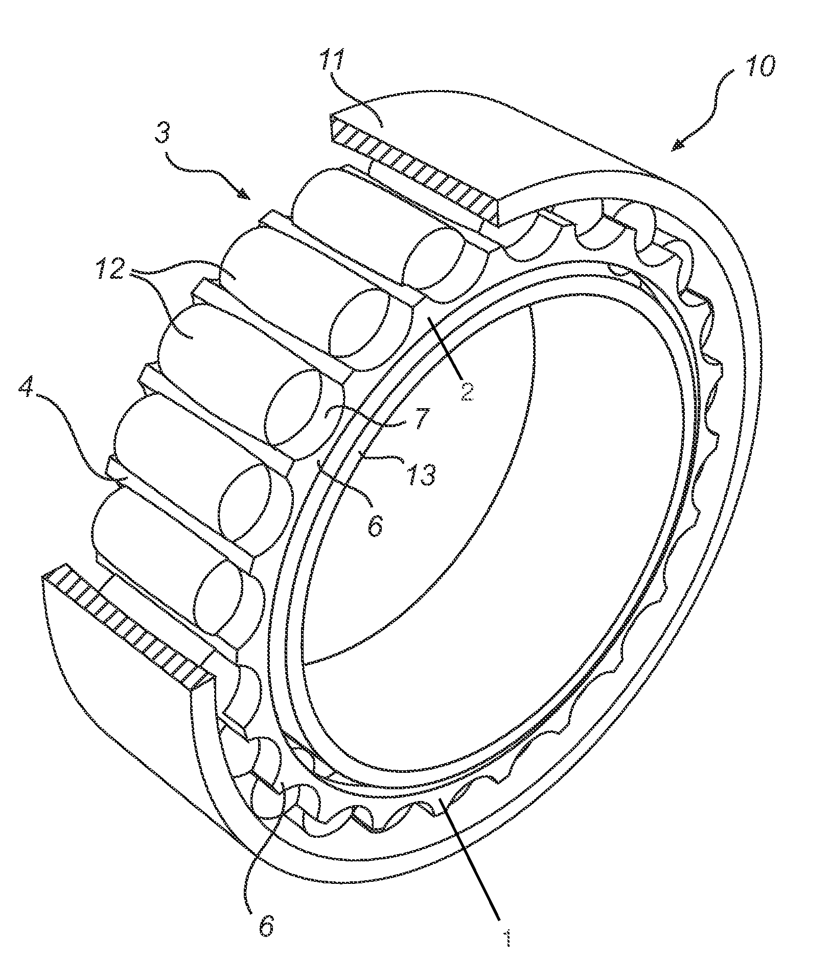
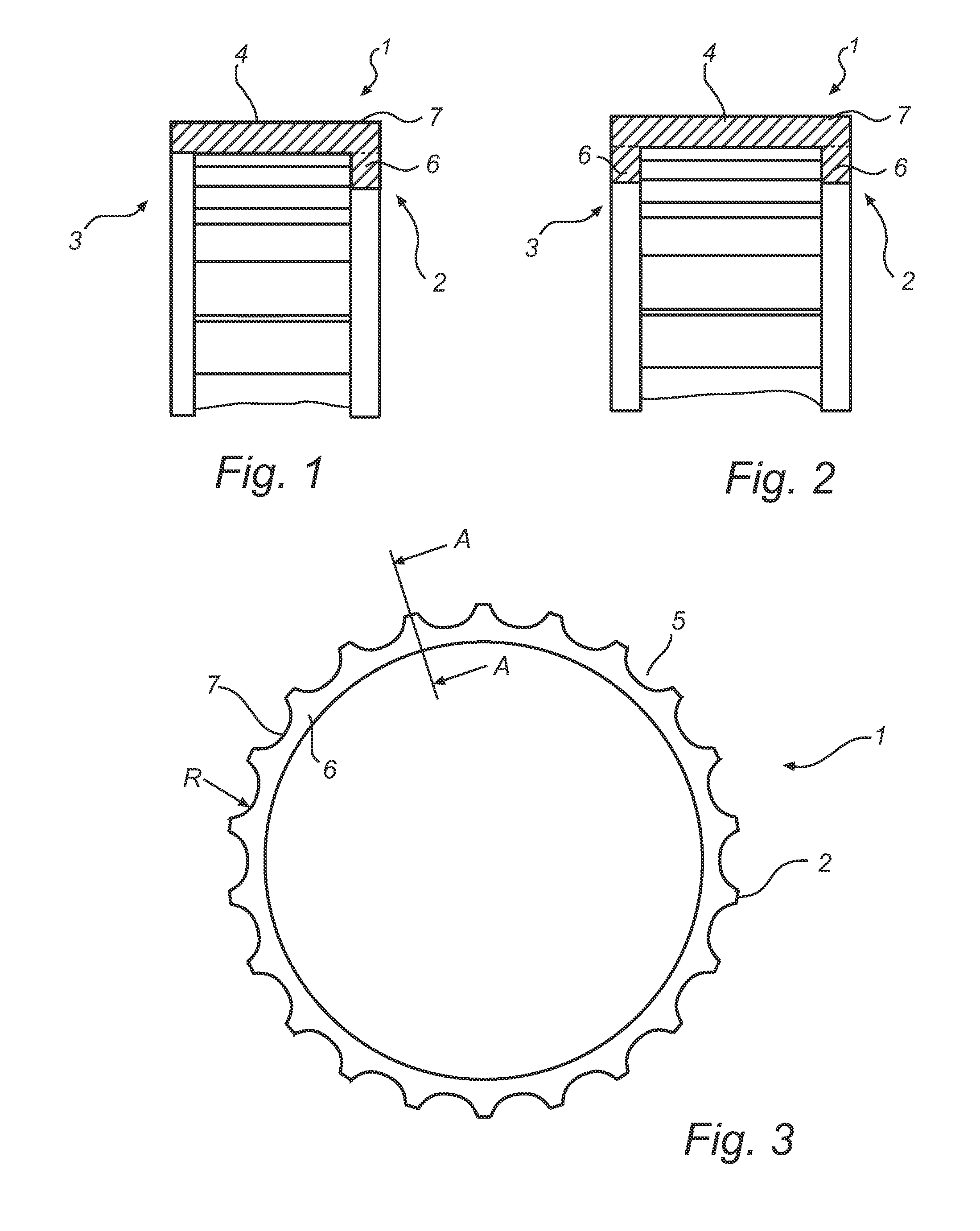
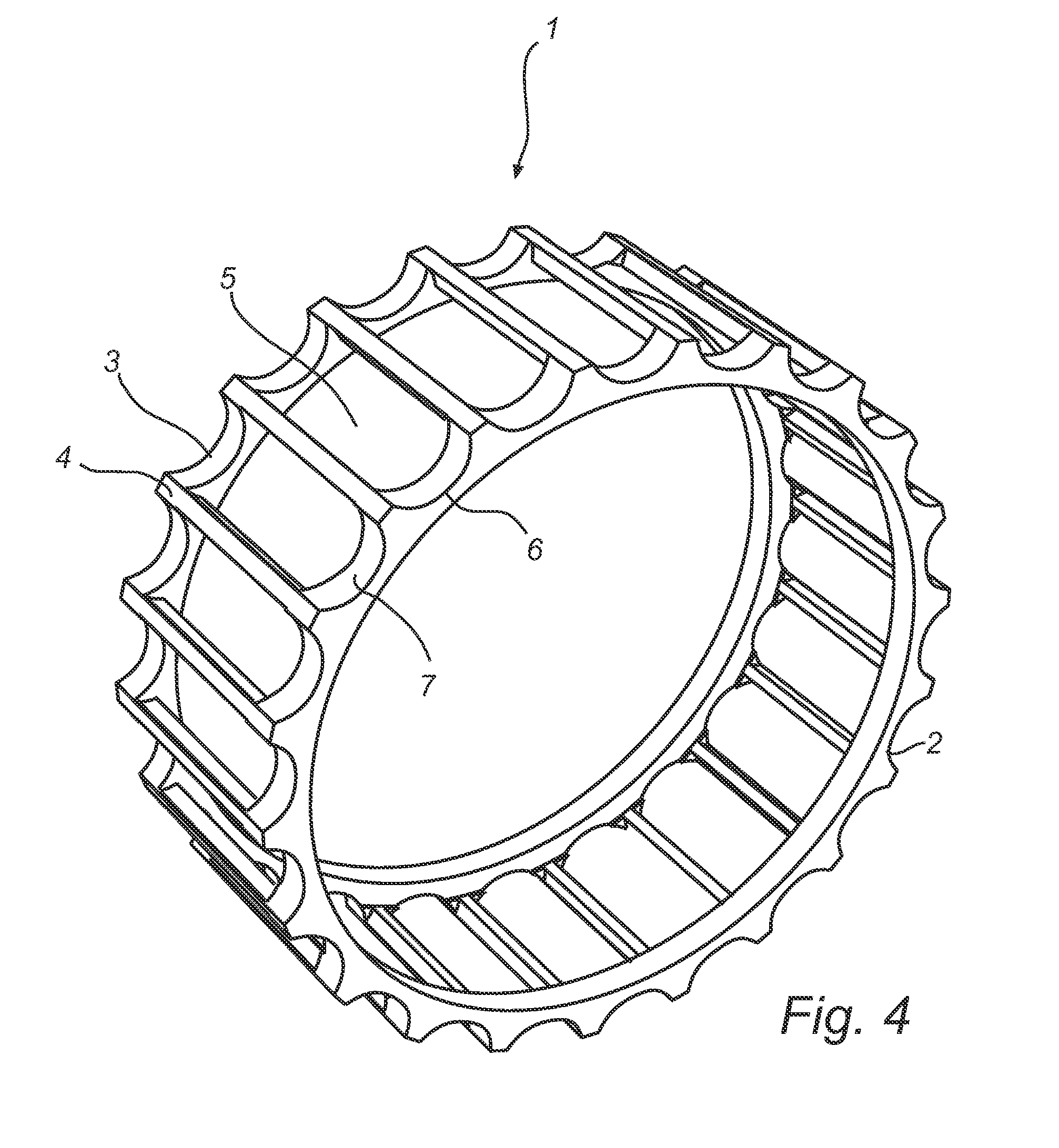
[0033]FIG. 1 shows a cross section of a cage 1 according to the invention. The cross section is a cross section of a plane intersecting the axial center line of the cage 1. Furthermore, the cross section is a cross section along a line A-A of FIG. 3. The cage 1 presents a first annular ring 2, a second annular ring 3 and elongated axial members 4 (one indicated in the figure). The axially elongated members 4 may also be called pins or lateral bars or any other appropriate name recognized by a skilled person. The two annular rings 2 and 3 and two adjacent axial elongated members 4 form a roller pocket 5 (not indicated in this figure). The roller pocket 5 is meant to receive a roller element of a toroidal roller bearing. The function of the cage is to retain and guide the roller elements of the roller bearing. Furthermore, the cage 1 presents a radially inwardly extending portion 6 on ...


PUM

PropertyMeasurementUnit
Shapeaaaaaaaaaa
Radiusaaaaaaaaaa
Friction coefficientaaaaaaaaaa

Abstract

The invention presents a cage (1) for separating rollers in a toroidal roller bearing. The cage (1) comprises a first and second annular ring (2, 3), a plurality of elongated axial members (4) interposed between the first and second annular ring to thereby form a number of roller pockets (5). The cage further presents a portion (6) extending radially inwardly on at least one of the first and second annular ring. The portion further extends in at least a part of the circumference of the at least one first and second annular ring. The radially outer peripheral surface of the annular ring presenting the portion presents axial grooves (7) at least at the circumference having the portion, wherein each axial groove is located at the axial end face of each roller pocket in such a way that a roller can be inserted and pulled out via the axial groove into and out of each roller pocket.

Description

TECHNICAL FIELD OF THE INVENTION[0001]According to a first aspect, the invention concerns a cage for a toroidal roller bearing.[0002]According to a second aspect, the invention concerns a toroidal roller bearing having a cage according to the first aspect of the invention.[0003]According to a third aspect, the invention concerns a method for assembling or dismounting a toroidal roller bearing.BACKGROUND OF THE INVENTION[0004]Toroidal roller bearings are well known. The bearing type is characterized by its ability to be able to angularly misalign and axially displace the inner ring and the outer ring of the bearing. This functionality is advantageous in several different types of applications. One common bearing set up on an axle is to mount one toroidal roller bearing, the non-locating bearing, at a first position and to mount a spherical roller bearing, the locating bearing, at a second position. There are obviously many other types of bearing arrangements possible with a toroidal ...

Claims


Application Information

Patent Timeline
IPC IPC(8): F16C33/46F16C23/08F16C43/06
CPCF16C33/4623F16C43/065F16C33/4635F16C23/08F16C19/26F16C43/08F16C33/4682F16C43/06F16C2300/02Y10T29/49698Y10T29/4968B21D53/12F16C23/086
Inventor KULLIN, ARNE LARS JONAS
Owner AB SKF
Why Eureka
Try Eureka