
Hydraulic pressure supply system of automatic transmission

a technology of automatic transmission and which is applied in the direction of pumping plant, transportation and packaging, and functional valve types, etc., can solve the problems of increasing manufacturing costs and increasing the number of components according to a conventional hydraulic pressure supply system, and achieve the effect of enhancing control responsiveness

Inactive Publication Date: 2014-06-12
HYUNDAI MOTOR CO LTD
View PDF6 Cites 6 Cited by
  • Summary
  • Abstract
  • Description
  • Claims
  • Application Information

AI Technical Summary

Benefits of technology

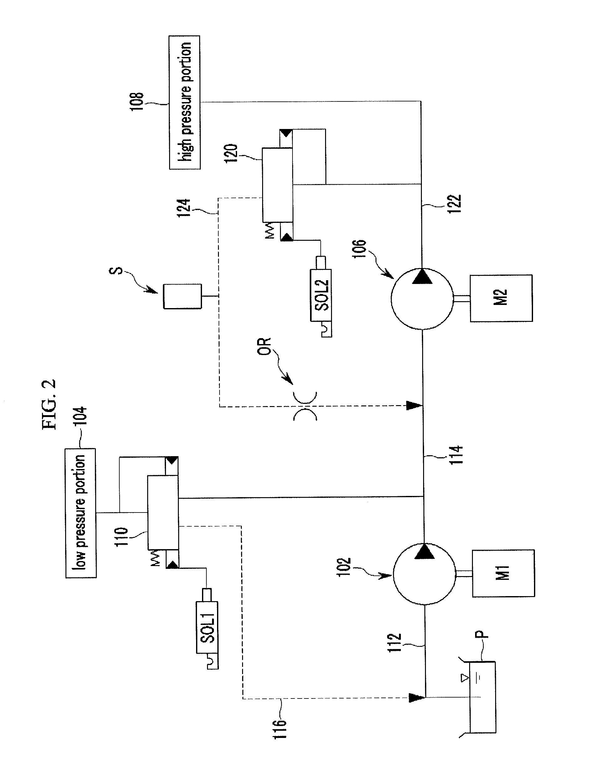
The present invention is about a hydraulic pressure supply system for an automatic transmission in a vehicle. It uses information from one pressure sensor to control electric motors and optimize hydraulic pressure and oil amount at both high and low pressure points. This results in enhanced control responsiveness. In simple terms, the technical effect of this invention is to improve the performance and efficiency of hydraulic pressure supply in an automatic transmission.

Problems solved by technology

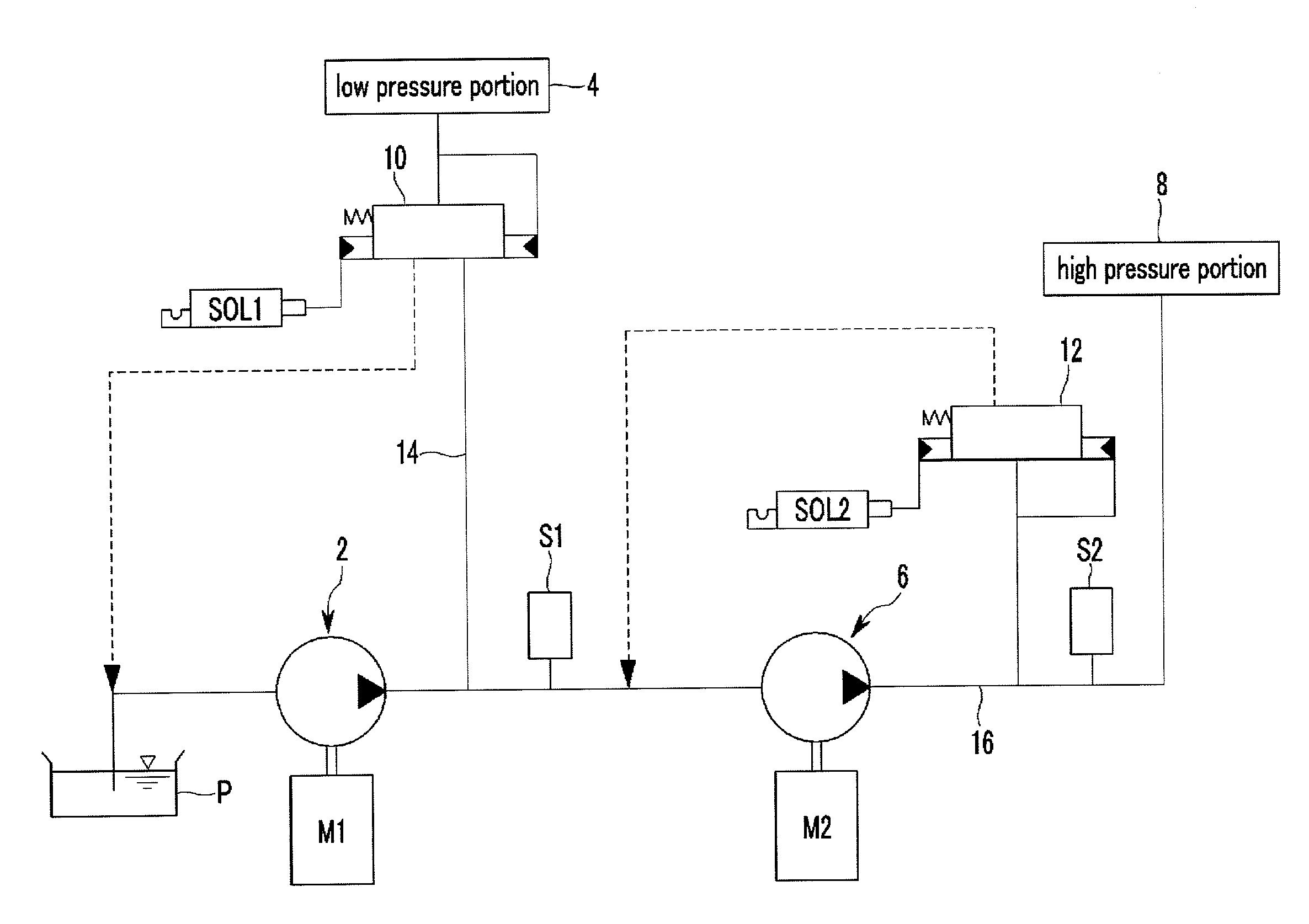
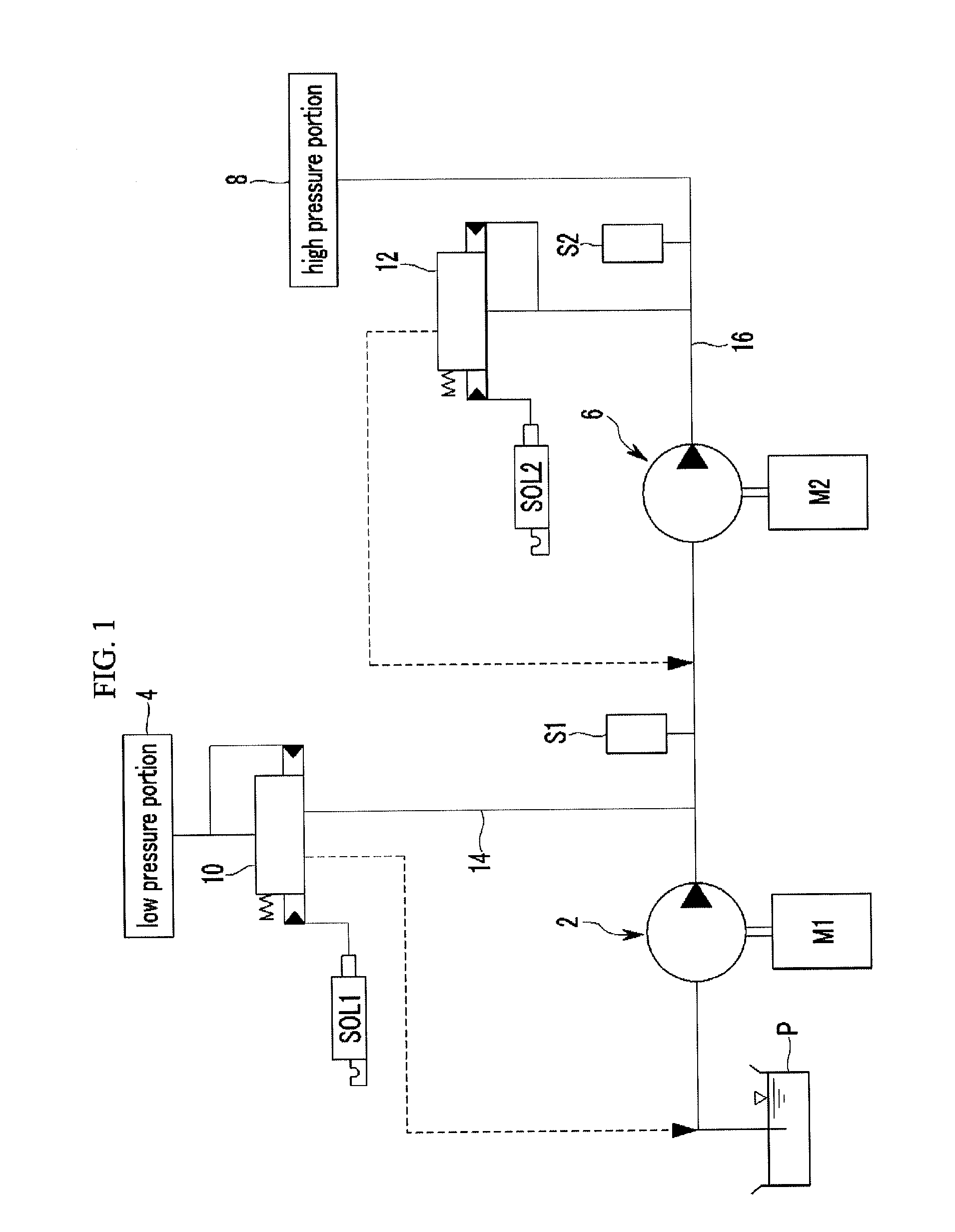
Since the first and second hydraulic pressure sensors S1 and S2 are used for controlling the rotation speeds of the low-pressure and high-pressure electric motors M1 and M2, however, the number of components may increase and manufacturing cost may also increase according to a conventional hydraulic pressure supply system.

Method used


Image

  • Hydraulic pressure supply system of automatic transmission
  • Hydraulic pressure supply system of automatic transmission
  • Hydraulic pressure supply system of automatic transmission

Examples


Embodiment Construction

[0032]Reference will now be made in detail to various embodiments of the present invention(s), examples of which are illustrated in the accompanying drawings and described below. While the invention(s) will be described in conjunction with exemplary embodiments, it will be understood that present description is not intended to limit the invention(s) to those exemplary embodiments. On the contrary, the invention(s) is / are intended to cover not only the exemplary embodiments, but also various alternatives, modifications, equivalents and other embodiments, which may be included within the spirit and scope of the invention as defined by the appended claims.

[0033]Description of components that are not necessary for explaining the illustrated embodiments will be omitted, and the same constituent elements are denoted by the same reference numerals in this specification.

[0034]In the detailed description, ordinal numbers are used for distinguishing constituent elements having the same terms,...


PUM


Abstract

A hydraulic pressure supply system of an automatic transmission for a vehicle may include a low-pressure hydraulic pump receiving oil stored in an oil pan through an input line, generating low hydraulic pressure using the oil, and supplying the low hydraulic pressure to a low pressure portion through a low-pressure line, and a high-pressure hydraulic pump increasing a portion of the low hydraulic pressure to high hydraulic pressure and supplying the high hydraulic pressure to a high pressure portion through a high-pressure line.

Description

CROSS-REFERENCE TO RELATED APPLICATION[0001]The present application claims priority of Korean Patent Application Number 10-2012-0144823 filed Dec. 12, 2012, the entire contents of which application is incorporated herein for all purposes by this reference.BACKGROUND OF INVENTION[0002]1. Field of Invention[0003]The present invention relates to a hydraulic pressure supply system of an automatic transmission for a vehicle. More particularly, the present invention relates to a hydraulic pressure supply system of an automatic transmission for a vehicle that can control an electric motor with optimized rotation speed by detecting whether target hydraulic pressure is formed at a high pressure portion and a low pressure portion.[0004]2. Description of Related Art[0005]Recently, vehicle makers direct all their strength to improve fuel economy due to worldwide high oil prices and strengthen of exhaust gas regulations.[0006]Improvement of fuel economy may be achieved by minimizing unnecessary ...

Claims


Application Information

Patent Timeline
Patent Type & Authority Applications(United States)
IPC IPC(8): F16H61/00
CPCF16H61/0021F16H61/0025F16H2061/0037F16H61/0206Y10T137/86002F16H61/431F16H61/42
Inventor JO, SE HWANHWANG, JIN YOUNGWI, TAEHWAN
Owner HYUNDAI MOTOR CO LTD
Learn More