System And Method For Mechanical And Membrane Oil-Water Separation

a technology of mechanical and membrane oil water and oil water, applied in the field of oilwater separation, can solve problems such as waste streams, and achieve the effect of reducing the amount of oil and reducing the amount of particulates

Inactive Publication Date: 2014-06-12
WATER PLANET ENG
View PDF4 Cites 88 Cited by
  • Summary
  • Abstract
  • Description
  • Claims
  • Application Information

AI Technical Summary

Benefits of technology

[0008]In accordance with another preferred embodiment of the present invention there is provided a method for separating water and oil from a mixture of water, oil, and particulates. The method comprises the steps of: flowing a first mixture of oil, water, and particulates into a vessel to reduce the amount of particulates in the first mixture to thereby form a second mixture of primarily oil and water; flowing the second mixture of oil and water through a separator to reduce the amount of oil in the second mixture thereby forming a third mixture; and flowing the third mixture into the vessel and the separator to further reduce the amount of oil in the third mixture.

Problems solved by technology

Current oil-water separation techniques require large hold-up volumes and often result in the production of waste streams comprised of highly mixed oil-and-water emulsions.

Method used


Image

  • System And Method For Mechanical And Membrane Oil-Water Separation
  • System And Method For Mechanical And Membrane Oil-Water Separation
  • System And Method For Mechanical And Membrane Oil-Water Separation

Examples


example

Influent “C”

[0037]

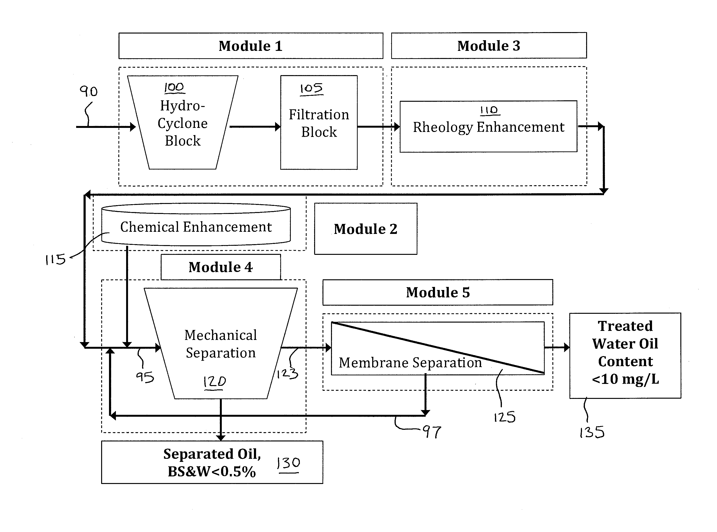
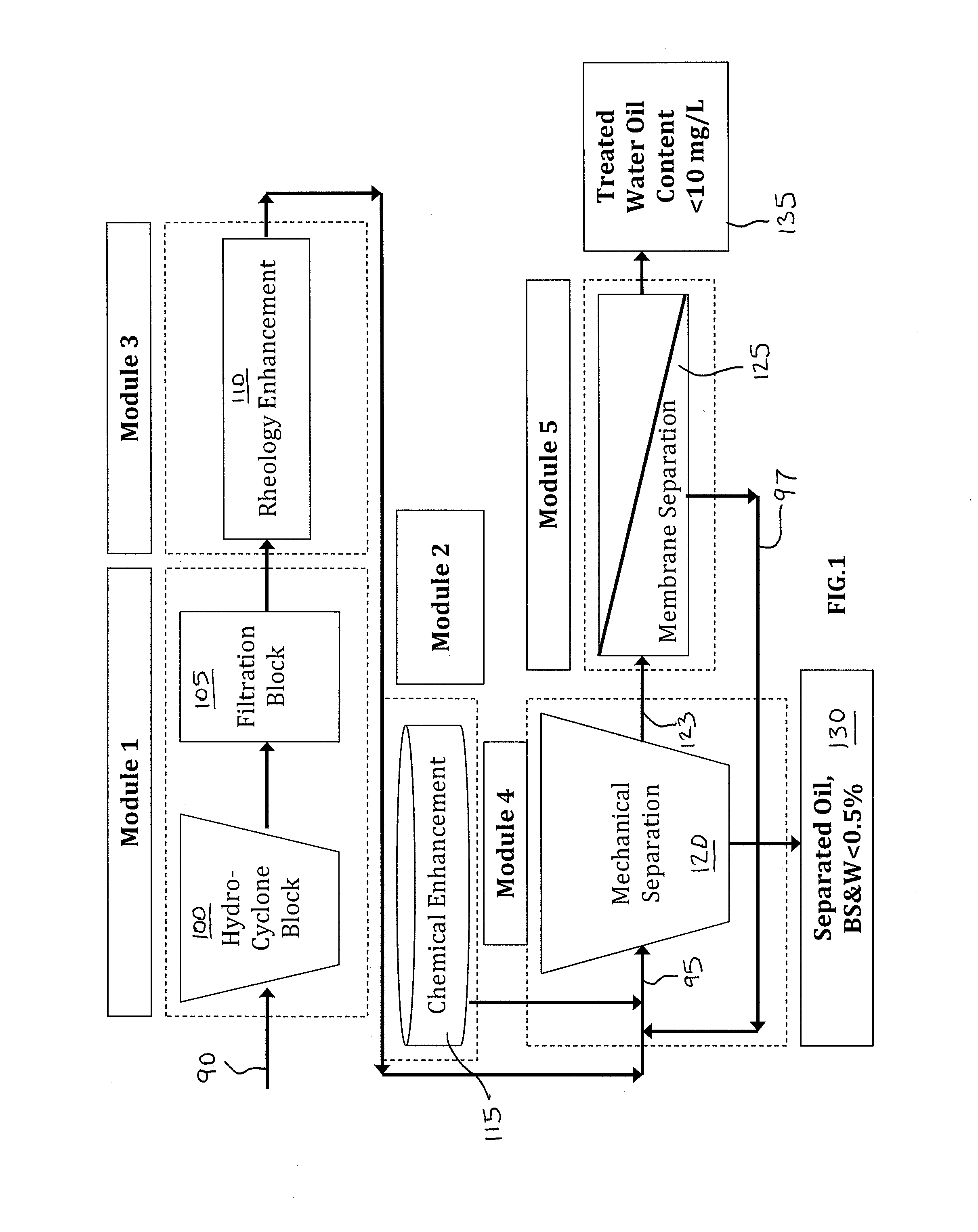
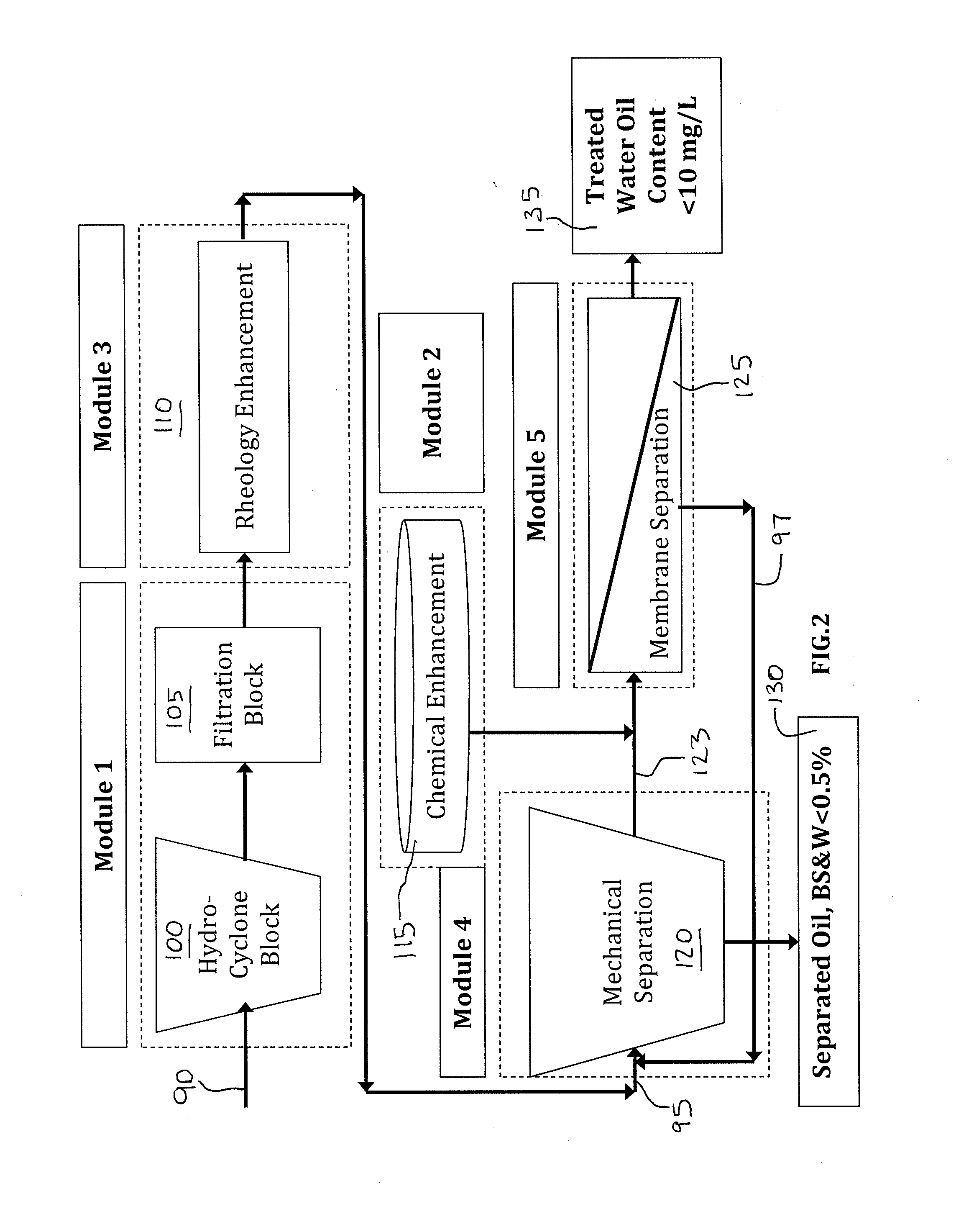
TABLE C-1Operational Inputs for Influent “C” Example:Oil Effluent WaterWater Effluent OilContent (Vol. %)Content (Vol. %)Unit A950.02Unit B100.5Unit CMembrane Pre-treatment60%Oil RemovalMembrane Rejection99%Membrane permeate75%recovery

TABLE C-2Influent “C” Example: Specifications for Stream 1 (Influent 1at input 95), Stream 2 (Effluent 2A at output 135),and Stream 3 (Effluent 1B at output 130):Flow Rates (GPM)Oil / WaterStreamOilWaterconcentration10.03 29.97Oil Content: 0.1 vol. %53 × 10−529.94Oil Content: 1 mg / L90.0250.003BS&W Content: 10 vol. %

TABLE C-3Influent “C” Example: Separated oil andtreated water recovery and waste production (showinginvention's ability to minimize waste streams):Flow rate (GPM)Yield (%)Oil0.02583.77Water29.9499.89Overall Influent Recovery99.88%Waste0.12


PUM

PropertyMeasurementUnit
chemical dosingaaaaaaaaaa
rheologyaaaaaaaaaa
particle sizeaaaaaaaaaa

Abstract

A system for the separation of the components of an oil, water, and solids mixture, the system comprising a mechanical separation module comprising an oily water output and an input adapted to receive an oil, water, and solids mixture; and a membrane separation module comprising an oily water input and a recirculation output. The oily water output of the mechanical separation module is in flow communication with the oily water input of the membrane separation module, and the recirculation output of the membrane separation module is in flow communication with the input of the mechanical separation module.

Description

CROSS REFERENCE TO RELATED APPLICATION[0001]This application claims the benefit of U.S. Provisional Patent Application No. 61 / 646,504, filed on May 14, 2012, the entirety of which is incorporated herein by reference.FIELD OF THE INVENTION[0002]The present invention relates generally to oil-water separation, more particularly, to a system and method for mechanical and membrane oil-water separation.BACKGROUND OF THE INVENTION[0003]The technical field of oil-water separation applies to the production of oil and gas as well as industrial wastewater treatment sectors. Conventional oil and water separation technologies generally use residence time, temperature, and gravity to separate a three-phase solid-oil-water emulsion. Current oil-water separation techniques require large hold-up volumes and often result in the production of waste streams comprised of highly mixed oil-and-water emulsions.[0004]Accordingly, a need exists for an improved separation system and method that helps solve th...

Claims


Application Information

Patent Timeline
Patent Type & Authority Applications(United States)
IPC IPC(8): C02F9/00C02F1/00C02F1/44C02F1/40C02F1/38
CPCC02F9/00B01D61/147C02F1/004C02F1/02C02F1/38C02F1/385C02F1/40C02F1/44C02F2101/32C02F2101/325C02F2301/08
Inventor HOEK, ERIC M.V.BHATTACHARJEE, SUBIREDALAT, ARIANTANUWIDJAJA, DIAN
Owner WATER PLANET ENG
Why Eureka
Try Eureka