

Stapler
a stapler and bending technology, applied in the field of staplers, can solve the problems of unstable motion of the bending member, unstable stapling motion, unstable bending member motion, etc., and achieve the effect of reliably performing the stapling operation, stable operation of each member, and reliable stapling operation
- Summary
- Abstract
- Description
- Claims
- Application Information
AI Technical Summary
Benefits of technology
Problems solved by technology
Method used
Image

Examples
Embodiment Construction
[0099]An exemplary embodiment of a stapler according to the present invention will be described with reference the accompanying drawings.
[0100]Exemplary Configuration of Stapler of the Embodiment
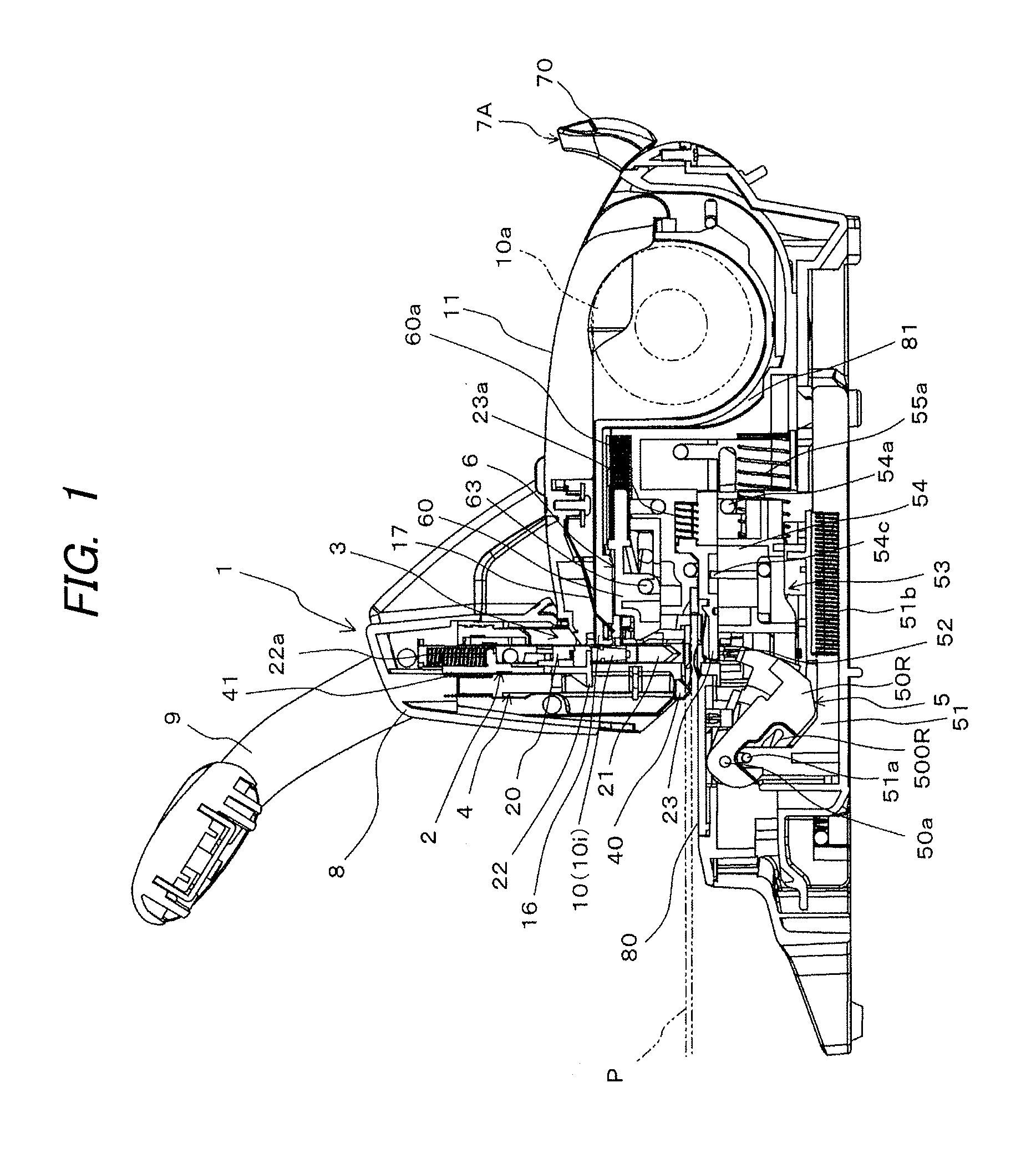
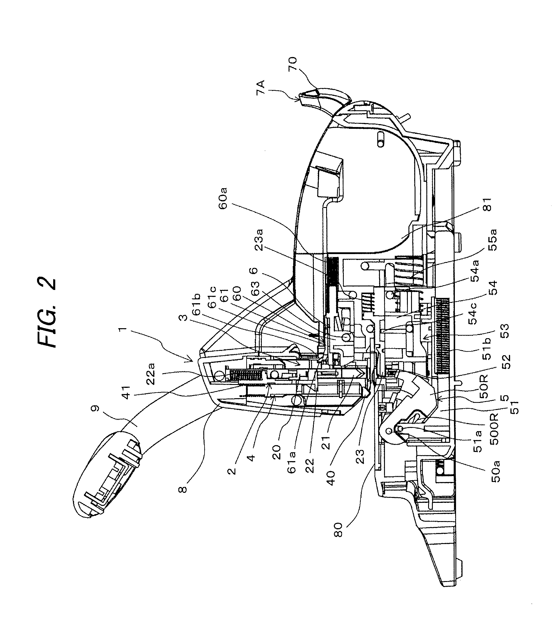
[0101]FIGS. 1 and 2 are side sectional views illustrating one example of the internal configuration of the stapler according to the embodiment, in which FIG. 1 shows a mounting state of a staple cartridge, and FIG. 2 shows a detached state of the staple cartridge. FIG. 3 is a side view illustrating one example of the stapler according to the embodiment.
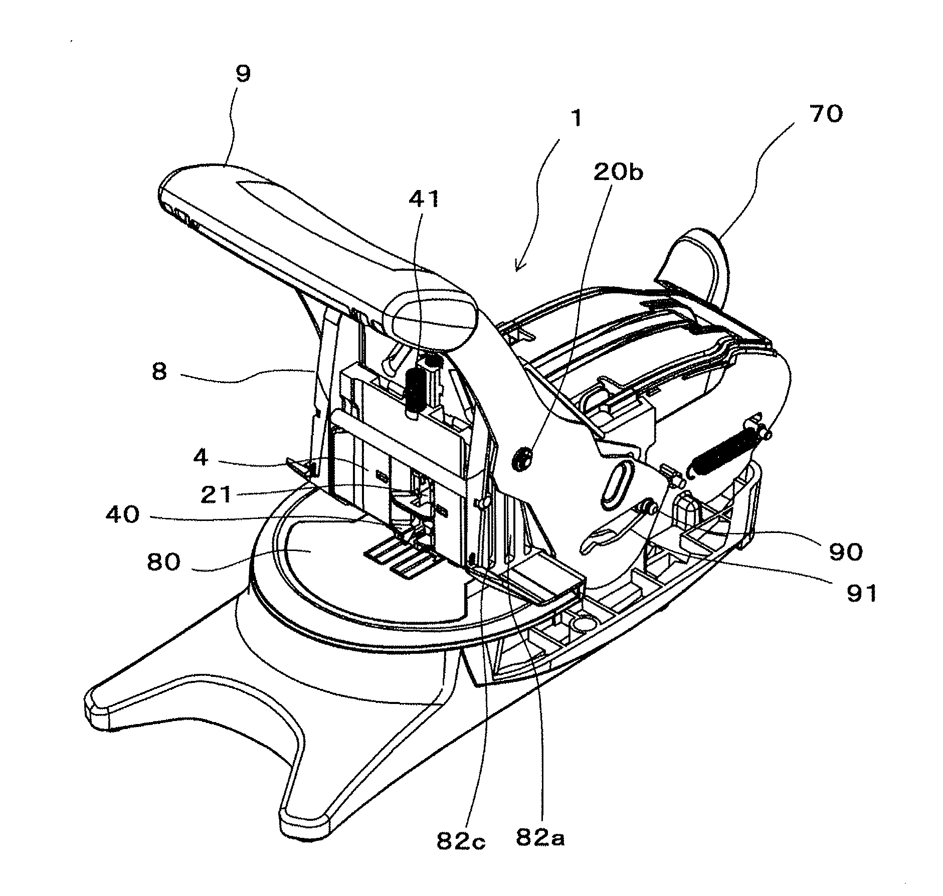
[0102]FIG. 4 is a perspective view illustrating one example of the stapler according to one embodiment when seen from a front. FIG. 5 is a perspective view illustrating one example of the stapler according to this embodiment when seen from a rear. FIG. 6 is a forward sectional view illustrating one example of the internal configuration in a penetrating mechanism of the stapler according to this embodiment. FIG. 7 is a forward sectional view il...
PUM
 Abstract
Description
Claims
Application Information