Printing apparatus, treatment object modifying apparatus, printing system, and printed material manufacturing method

a technology of modifying apparatus and printing system, which is applied in printing, duplicating/marking methods, plasma techniques, etc., can solve the problems of image failure, image quality reduction, and difficulty in improving throughput for high-speed printing

Active Publication Date: 2014-06-12
RICOH KK
View PDF3 Cites 28 Cited by
  • Summary
  • Abstract
  • Description
  • Claims
  • Application Information

AI Technical Summary

Benefits of technology

[0009]It is an object of the present invention to at least

Problems solved by technology

In conventional inkjet recording apparatuses, it is difficult to improve throughput for high-speed printing because a shuttle head that moves back and forth in a width direction of a recording medium, such as a sheet of paper or a film, is generally used.
Therefore, coalescence of the adjacent dots (hereinafter, may be referred to as impact interference) occurs, so that beading or bleed may occur with which the image quality is reduced.
Furthermore, if an inkjet printing apparatus prints an image on an impermeable medium or a low-permeable medium, such as a film or a coated paper, adjacent dots move and coalesce together, resulting in an image failure, such as beading or bleed.
However, in the method to apply primer to a printing medium in advance, it

Method used


Image

  • Printing apparatus, treatment object modifying apparatus, printing system, and printed material manufacturing method
  • Printing apparatus, treatment object modifying apparatus, printing system, and printed material manufacturing method
  • Printing apparatus, treatment object modifying apparatus, printing system, and printed material manufacturing method

Examples


Embodiment Construction

[0039]Exemplary embodiments of the present invention will be explained in detail below with reference to the accompanying drawings. The embodiments below are described as preferable embodiments of the present invention, and therefore, various technically-preferable limitations are applied. However, the scope of the present invention is not unreasonably limited by the descriptions below. Furthermore, not all of the constituent elements described in the embodiments is necessary to embody the present invention.

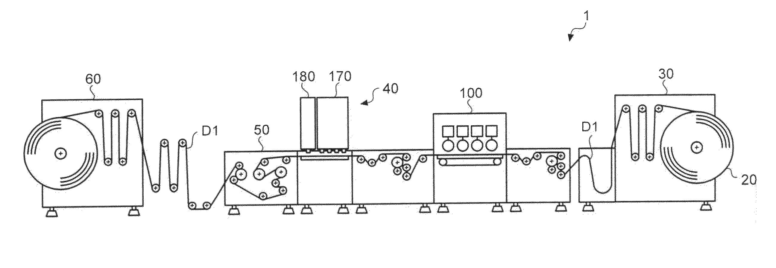
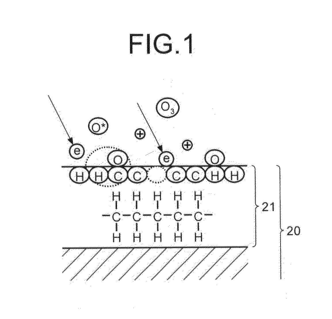
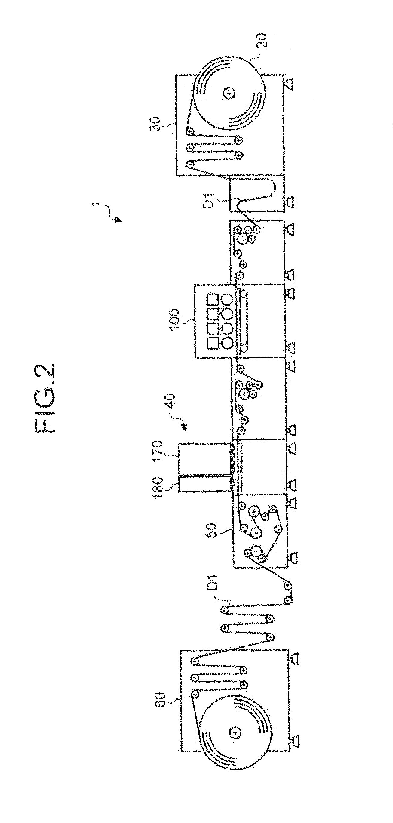
[0040]In an embodiment described below, to prevent dispersion of ink pigments and aggregate the pigments immediately after ink droplets have dropped on a treatment object (also referred to as a recording medium or a printing medium), the surface of the treatment object is acidified. Plasma treatment will be described below as an example of an acidification method.

[0041]Furthermore, in the embodiment, wettability of a surface of a treatment object subjected to the plasma treatment...


PUM

PropertyMeasurementUnit
Diameteraaaaaaaaaa
Sizeaaaaaaaaaa
Densityaaaaaaaaaa

Abstract

A printing apparatus includes a plasma treatment unit that performs plasma treatment on a surface of a treatment object to acidify at least the surface of the treatment object, a recording unit that performs an inkjet recording process on the surface of the treatment object subjected to the plasma treatment by the plasma treatment unit, and a control unit that adjusts plasma energy for the plasma treatment according to a type of an ink used in the inkjet recording process.

Description

CROSS-REFERENCE TO RELATED APPLICATIONS[0001]The present application claims priority to and incorporates by reference the entire contents of Japanese Patent Application No. 2012-271716 filed in Japan on Dec. 12, 2012 and Japanese Patent Application No. 2013-216724 filed in Japan on Oct. 17, 2013.BACKGROUND OF THE INVENTION[0002]1. Field of the Invention[0003]The present invention relates to a printing apparatus, a treatment object modifying apparatus, a printing system, and a printed material manufacturing method.[0004]2. Description of the Related Art[0005]In conventional inkjet recording apparatuses, it is difficult to improve throughput for high-speed printing because a shuttle head that moves back and forth in a width direction of a recording medium, such as a sheet of paper or a film, is generally used. Therefore, in recent years, to cope with the high-speed printing, a single-pass system has been proposed, in which a plurality of heads are arranged so as to cover the entire wi...

Claims


Application Information

Patent Timeline
IPC IPC(8): B41J11/00
CPCB41J11/0015B41M5/0011B41M5/0041B41M5/0047B41M5/0064H05H1/2406H05H1/2431
Inventor HIROSE, YOHJIYOSHIDA, MASAKAZUOSANAI, TOSHITAKA
Owner RICOH KK
Why Eureka
Try Eureka