Solid-state battery

a solid-state battery and battery body technology, applied in the field of solid-state batteries, can solve the problems of difficult to increase the size of the electrode area and powder compression molding may not be suitable for the preparation of high-capacity solid-state batteries, and achieve the effect of improving the lifetime characteristics

Active Publication Date: 2014-06-12
SAMSUNG ELECTRONICS CO LTD
View PDF20 Cites 25 Cited by
  • Summary
  • Abstract
  • Description
  • Claims
  • Application Information

AI Technical Summary

Benefits of technology

[0009]Provided is a solid-state battery having improved lifetime characteristics.

Problems solved by technology

However, in the preparation method by powder compression molding, since a container and a pressure device that correspond to a size of an electrode area (i.e., an area in which the electrode is in contact with the electrolyte layer) is used, it may be difficult to increase the size of the electrode area.
Therefore, powder compression molding may not be suitable for the preparation of a high capacity solid-state battery, which is currently in demand.

Method used


Image

  • Solid-state battery
  • Solid-state battery
  • Solid-state battery

Examples


example 1

Adhesive Layer Formation

[0136]Graphite (KS-4, Timcal, hereinafter the same), acetylene black (DENKA, hereinafter the same) as an adhesive layer conductive material, a styrene-based thermoplastic elastomer (hereinafter, referred to as “binder A”) (S.O.E1611, Asai Kasei Corporation, hereinafter the same) as a first binder, and acid modified polyvinylidene fluoride (“PVDF”) (hereinafter, referred to as “binder B”) (KF9200, Kureha Corporation, hereinafter the same) as a third binder were weighed at a weight percent ratio of about 60:10:15:15. Then, the above materials and an appropriate amount of NMP were introduced into a planetary mixer and mixed at about 3,000 revolutions per minute (“RPM”) for about 5 minutes to prepare an adhesive layer coating solution.

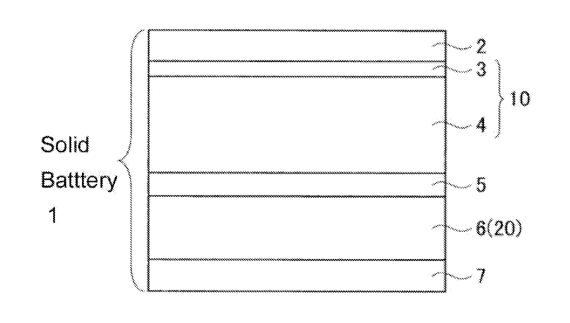
[0137]Next, an about 20 micrometer (μm) thick aluminum foil current collector, as the cathode current collector 2, was disposed on a desktop screen printer (Newlong Seimitsu Kogyo Co., Ltd., hereinafter the same), and the aluminum f...

example 2

Cathode Structure Formation

[0148]A cathode structure was formed in the same manner as in Example 1. Anode layer Formation

[0149]Si alloy powder (vacuum dried at about 80° C. for about 24 hours) as an anode active material, binder A as a first binder, and binder C (polyamic acid type polyimide resin, HCI1000S, Hitachi Chemical Co., Ltd., elastic modulus of about 2.5 GPa) as a second binder were weighed at a weight percent ratio of about 94.5:0.5:5.0. The above materials and an appropriate amount of NMP were introduced into a planetary mixer and mixed at about 3,000 rpm for about 3 minutes. Then, an anode layer coating solution was prepared by performing a degassing treatment for about 1 minute.

[0150]Next, an about 16 μm thick copper foil current collector was prepared as the anode current collector 7, and the copper foil current collector was coated with the anode layer coating solution using a blade. A thickness (gap) of the anode layer coating solution on the copper foil current col...


PUM

PropertyMeasurementUnit
temperatureaaaaaaaaaa

Abstract

A solid-state battery including a cathode, an anode, and a solid-state electrolyte layer including a solid-state electrolyte, wherein the solid-state electrolyte layer is disposed between the cathode and the anode, wherein the anode includes an anode active material, a first binder, and a second binder, the first binder is inactive to the solid-state electrolyte, the second binder has a tensile modulus greater than a tensile modulus of the first binder, and the second binder has a binding force which is greater than a binding force of the first binder.

Description

RELATED APPLICATIONS[0001]This application claims priority to and the benefit of Japanese Patent Application No. 2012-268537, filed on Dec. 7, 2012, and Korean Patent Application No. 10-2013-0101289, filed on Aug. 26, 2013, and all the benefits accruing therefrom under 35 U.S.C. §119, the contents of which are incorporated herein in their entirety by reference.BACKGROUND[0002]1. Field[0003]The present disclosure relates to a solid-state battery. The solid-state battery may be a lithium-ion secondary battery, or the like.[0004]2. Description of the Related Art[0005]A lithium-ion secondary battery can be a solid-state battery using a solid-state electrolyte. The solid-state battery may include an electrolyte layer including a solid-state electrolyte, electrodes (cathode and anode) formed on opposite surfaces of the electrolyte layer, and current collectors that are respectively bonded to the electrodes. In the solid-state battery, in general, since the solid-state electrolyte is used ...

Claims


Application Information

Patent Timeline
Patent Type & Authority Applications(United States)
IPC IPC(8): H01M4/62H01M10/0525H01M10/0562H01M4/133H01M4/134
CPCH01M4/133H01M4/134H01M4/622H01M4/623H01M10/0525H01M10/0562Y02E60/10
Inventor HOSHIBA, KOJIFUJIKI, SATOSHIYAMADA, TAKANOBUAIHARA, YUICHI
Owner SAMSUNG ELECTRONICS CO LTD
Why Eureka
Try Eureka