
Organic electroluminescent compound and organic electroluminescent device comprising the same

一种化合物、致发光的技术,应用在电致发光光源、有机化学、电光源等方向,能够解决低玻璃化转变温度、有机电致发光装置工作寿命短、没有具体公开等问题,达到低驱动电压的效果

Active Publication Date: 2019-03-08
ROHM & HAAS ELECTRONICS MATERIALS LLC
View PDF2 Cites 22 Cited by
  • Summary
  • Abstract
  • Description
  • Claims
  • Application Information

AI Technical Summary

Problems solved by technology

[0005] Although these materials offer good light-emitting properties, they have the following disadvantages: (1) Due to their low glass transition temperature and poor thermal stability, they may degrade in vacuum during the high-temperature deposition process, and the lifetime of the device is reduced
Therefore, there is no advantage in terms of power efficiency (lm / W)
(3) Further, when these materials are used in organic electroluminescent devices, the operating life of organic electroluminescent devices is short, and there is still a need to improve luminous efficiency
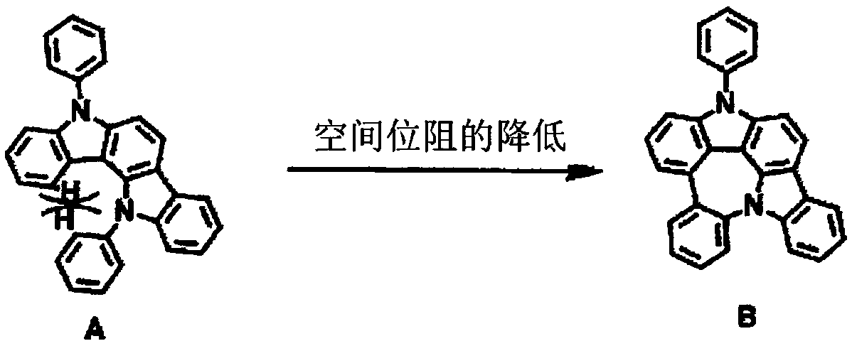
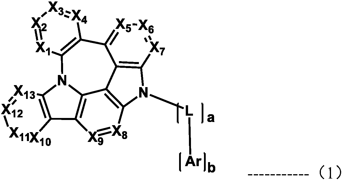
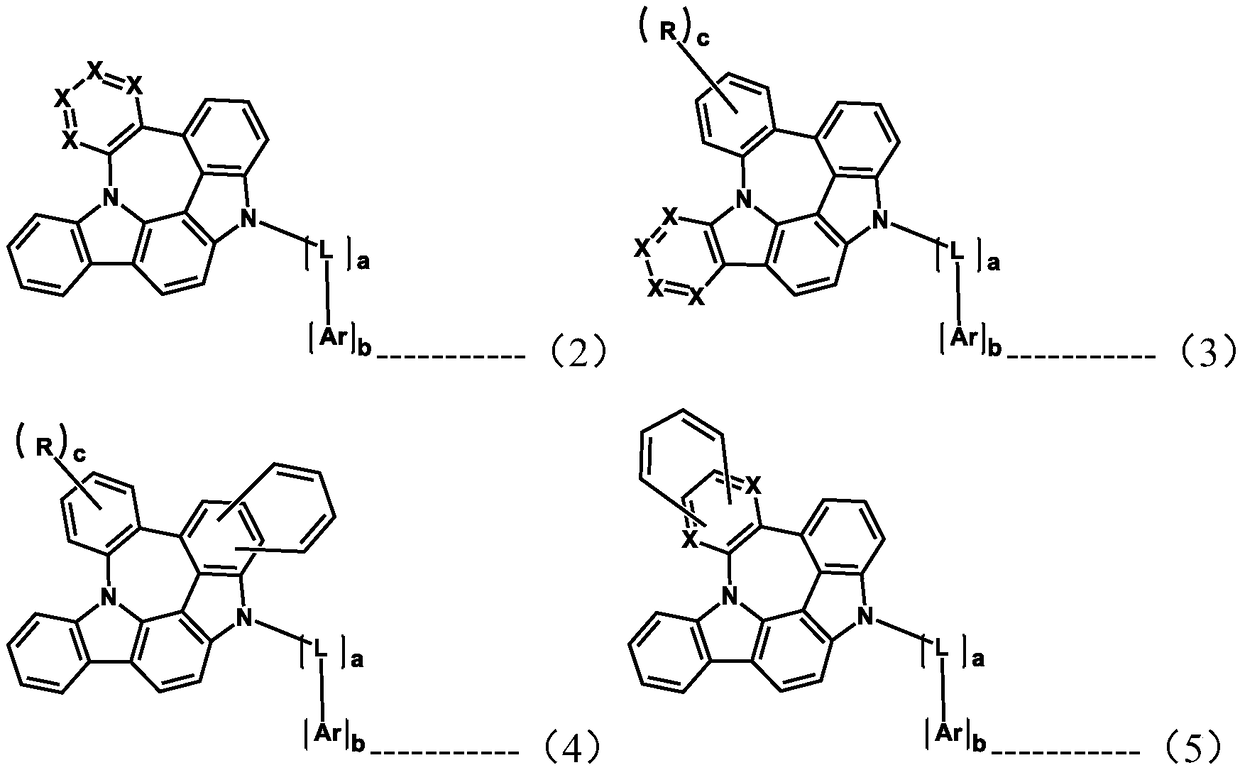
However, the reference does not specifically disclose compounds including a fused structure of indolocarbazole and azepine

Method used


Image

  • Organic electroluminescent compound and organic electroluminescent device comprising the same
  • Organic electroluminescent compound and organic electroluminescent device comprising the same
  • Organic electroluminescent compound and organic electroluminescent device comprising the same

Examples


example 1

[0117] Example 1: Preparation of Compound C-50

[0118]

[0119] Preparation of compound 1-1

[0120] 36g compound A (125.38mmol), 27g 3-bromo-2-chloro-nitrobenzene (113.98mmol), 4g tetrakis (triphenylphosphine) palladium (3.42mmol), 30g sodium carbonate (284.95mmol), 570mL toluene , 140 mL of ethanol, and 140 mL of distilled water were introduced into the reaction vessel, and the mixture was stirred at 120° C. for 3 hours. After the reaction was completed, the mixture was cooled to room temperature, and extracted with ethyl acetate. The extracted organic layer was then dried with magnesium sulfate, and the solvent was removed using a rotary evaporator. After that, the resulting product was purified by column chromatography to obtain 30 g of Compound 1-1 (yield: 66%).

[0121] Preparation of compound 1-2

[0122] 27g of compound 1-1 (68.20mmol), 1.5g of palladium (II) acetate (6.82mmol), 5.0g of tricyclohexylphosphonium tetrafluoroborate (13.64mmol), 66g of cesium...

example 2

[0128] Example 2: Preparation of Compound C-51

[0129]

[0130]5g compound 1-3 (15mmol), 8.6g 2-(4-bromonaphthalen-1-yl)-4,6-diphenyl-1,3,5-triazine (20mmol), 0.4g palladium acetate (II) (2 mmol), 1.2 g of soil inorganic phosphorus (3 mmol), 2.2 g of sodium tert-butoxide (23 mmol), and 76 mL of o-xylene were introduced into a reaction vessel, and the mixture was stirred under reflux for 3 hours. After the reaction was completed, the mixture was washed with distilled water, extracted with ethyl acetate, and the extracted organic layer was dried with magnesium sulfate. The solvent was removed with a rotary evaporator, and the resulting product was purified by column chromatography to obtain 3.3 g of Compound C-51 (yield: 32%).

[0131]

example 3

[0132] Example 3: Preparation of Compound C-49

[0133]

[0134] 6g compound 1-3 (18mmol), 8.5g 2-(4-bromophenyl)-4,6-diphenyl-1,3,5-triazine (22mmol), 0.4g palladium (II) acetate ( 2 mmol), 1.5 g of soil inorganic phosphorus (4 mmol), 2.6 g of sodium tert-butoxide (27 mmol), and 91 mL of o-xylene were introduced into the reaction vessel, and the mixture was stirred under reflux for 2 hours. After the reaction was completed, the mixture was washed with distilled water, extracted with ethyl acetate, and the extracted organic layer was dried with magnesium sulfate. The solvent was removed with a rotary evaporator, and the resulting product was purified by column chromatography to obtain 10 g of compound C-49 (yield: 86%).

[0135]


PUM


Abstract

The present disclosure relates to an organic electroluminescent compound and an organic electroluminescent device comprising the same. By using the organic electroluminescent compound of the present disclosure, an organic electroluminescent device having low driving voltage, high luminous efficiency, and / or excellent lifespan characteristic can be produced.

Description

technical field [0001] The present disclosure relates to an organic electroluminescent compound and an organic electroluminescent device including the organic electroluminescent compound. Background technique [0002] Among display devices, an electroluminescent device (EL device) is a self-luminous device that is advantageous in providing a wider viewing angle, a larger contrast ratio, and a faster response time. The first organic EL device was developed by Eastman Kodak in 1987 by using small aromatic diamine molecules and aluminum complexes as materials for forming the light emitting layer [Appl. Phys. Lett. 51,913, 1987]. [0003] The most important factor determining the luminous efficiency in an organic electroluminescent device is the luminescent material. Fluorescent materials have been widely used as light emitting materials so far. However, in view of the mechanism of electroluminescence, the development of phosphorescent light-emitting materials has been extens...

Claims


Application Information

Patent Timeline
Patent Type & Authority Applications(China)
IPC IPC(8): C07D487/16C09K11/06H01L27/32H01L51/50H01L51/54H05B33/14
CPCC07D487/16C07D471/22C07D487/22C09K11/06C09K2211/1011C09K2211/1014C09K2211/1029C09K2211/1044C09K2211/1059H10K59/00H10K85/615H10K85/631H10K85/626H10K85/636H10K85/633H10K85/654H10K85/6572H10K50/11C09B57/00H10K85/342H10K2101/10H10K50/15H10K2101/90C07D487/14C07D403/04C09K2211/1018
Inventor 文斗铉全志松
Owner ROHM & HAAS ELECTRONICS MATERIALS LLC
Learn More