Fibre laying machine comprising a roller with pivoting rings

a technology of pivoting rings and laying machines, which is applied in the direction of lap forming devices, lap winding devices, textiles and paper, etc., can solve the problems of bridging type defects, defects of wrinkling type defects, and impact on mechanical properties of components produced, so as to limit the interaction between pivoting rings

Active Publication Date: 2014-06-19
AIRBUS OPERATIONS (SAS)
View PDF4 Cites 9 Cited by
  • Summary
  • Abstract
  • Description
  • Claims
  • Application Information

AI Technical Summary

Benefits of technology

[0041]According to another feature, the pivoting rings are closely spaced in a direction parallel to the axis of rotation. This configuration makes it possible to limit the interactions between the pivoting rings.
[0042]According to a first alternative form, the body comprises a main body and a sleeve coaxial with the main body which comprises, on its exterior surface, circumferential grooves of a width equal to that of the pivoting rings, the grooves being separated by ribs which immobilize the pivoting rings in a direction parallel to the axis of rotation. According to this alternative form, the sleeve is made of a suitable material allowing it to deform when it is not fitted over the main body so as to fit the pivoting rings into the grooves.

Problems solved by technology

If the tension in a given fibre 22 is too high, it will cause bridging across a hollow in the component, as illustrated in FIG. 3B, and this bridging will remain included in the preform and lead to a defect that will have an impact on the mechanical properties of the component produced.
This last effect generally leads to defects for the following reasons.
Therefore, if Vext is greater than θ.R, the fibre Fext applied at this point is too highly tensioned, and this tends to cause defects of the bridging type as illustrated in FIG. 3B.
At the same time, if Vint is less than θ.R, the fibre Fint applied at this point is insufficiently tensioned, and this tends to cause defects of the wrinkling type as illustrated in FIG. 3A.
These polymerization techniques are generally more complicated to perform.
In addition, insofar as the fibres are not preimpregnated, they can slide relative to one another within the preform and fail to be correctly positioned in the end analysis.
However, this solution is difficult to put into practice because it entails changing the design of the laying head.
Thus, reducing the angle of wrap leads to impaired precision with which the fibres can be positioned in the longitudinal direction.
Even though it limits the risks of the appearance of defects of the bridging or wrinkling type, this solution is not entirely satisfactory because the roller is relatively complex.
Moreover, because each segment has a large radius of the order of 35 mm, the roller is unable to apply the fibres correctly against the application surface if the latter has an indentation of a radius of curvature smaller than 35 mm.

Method used


Image

  • Fibre laying machine comprising a roller with pivoting rings
  • Fibre laying machine comprising a roller with pivoting rings
  • Fibre laying machine comprising a roller with pivoting rings

Examples


Embodiment Construction

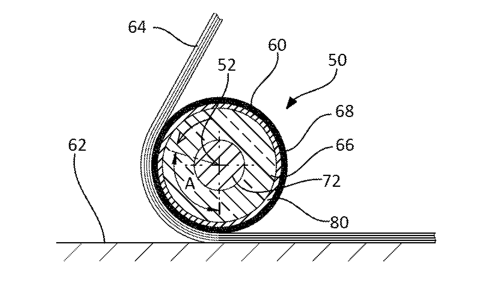
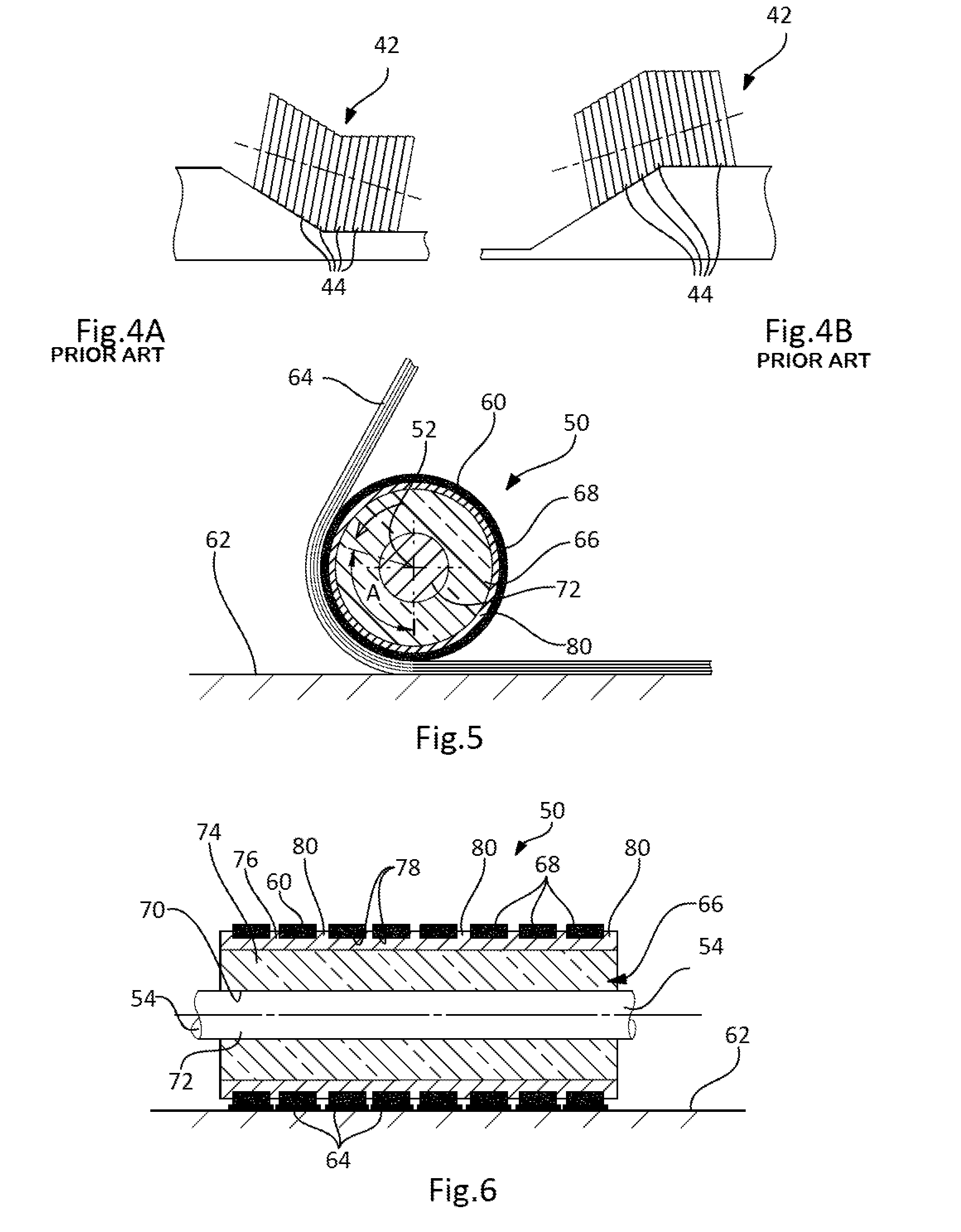
[0055]FIGS. 5 to 8 depict a roller 50 of a fibre laying machine able to pivot about an axis of rotation 52.

[0056]As in the prior art, the roller 50 comprises means for connecting it to a laying head. According to one embodiment, the roller 50 comprises at each end a stub shaft 54 pivot-mounted in a bearing of a support secured to the laying head. These guidances of the stub shafts 54 in their bearings define the axis of rotation 52. The laying machine, the connection between the roller and the laying head are not described in further detail because they are known to those skilled in the art and may be identical to those of the prior art inasmuch as the roller 50 according to an embodiment of the invention is more particularly suited to being mounted on existing fibre laying machines in place of the rollers of the prior art.

[0057]According to one embodiment, the roller 50 comprises a substantially cylindrical exterior surface 60 which can roll over an application surface 62 so as to ...


PUM

PropertyMeasurementUnit
widthaaaaaaaaaa
temperatureaaaaaaaaaa
radiusaaaaaaaaaa

Abstract

A fibre laying machine includes a laying head with a roller able to pivot about an axis of rotation and to apply a plurality of preimpregnated fibres to an application surface by rolling over the application surface. The fibres are distributed along a lower generatrix of the roller and in contact with an exterior surface of the roller over an angle of wrap. The roller includes a cylindrical body, pivoting rings around the body, and means for immobilizing the pivoting rings with respect to the body in a direction parallel to the axis of rotation.
The pivoting rings are able to pivot independently of one another.

Description

TECHNICAL FIELD[0001]The present invention relates to a fibre laying machine comprising a roller with pivoting rings.[0002]The invention relates more specifically to the preforms produced from fibres preimpregnated with resin which are then polymerized during a consolidation step that does not involve further addition of resin.BACKGROUND OF THE INVENTION[0003]According to one procedure, a component made of composite material is produced from a fibre preform subjected to a polymerization cycle.[0004]A preform here means a volume of fibres which are laid in a set arrangement, notably obtained by superposing layers of fibres on top of one another on a mould surface.[0005]When the surface of the mould is a developable surface, it is possible to use layup machines which seek to apply to the mould fibre plies the dimensions of which may be as large as those of the component. In such cases, each layer may consist of a single ply.[0006]When the surface of the mould is not a developable surf...

Claims


Application Information

Patent Timeline
Patent Type & Authority Applications(United States)
IPC IPC(8): D04H3/04
CPCB29C70/384D04H3/04
Inventor DE MATTIA, DENIS
Owner AIRBUS OPERATIONS (SAS)
Why Eureka
Try Eureka