Solar Heat Collector

a solar energy and heat collector technology, applied in the direction of solar heat collectors with working fluids, heat collector mounting/support, solar heat collector safety, etc., can solve the problems of increasing the number of problems caused, difficult to manufacture and heavy, and many components of collectors

Inactive Publication Date: 2014-06-19
FUNDACION CIDAUT
View PDF1 Cites 4 Cited by
  • Summary
  • Abstract
  • Description
  • Claims
  • Application Information

AI Technical Summary

Problems solved by technology

All of this results in collectors with many components that are consequently relatively expensive, difficult to manufacture and heavy.
The greater the number of components the longer the string of dimensions that must be combined, and therefore the greater the number of problems caused by component expansion.

Method used


Image

  • Solar Heat Collector
  • Solar Heat Collector
  • Solar Heat Collector

Examples


Embodiment Construction

[0009]The present invention is defined and characterized by the independent claims, while the dependent claims describe additional features thereof.

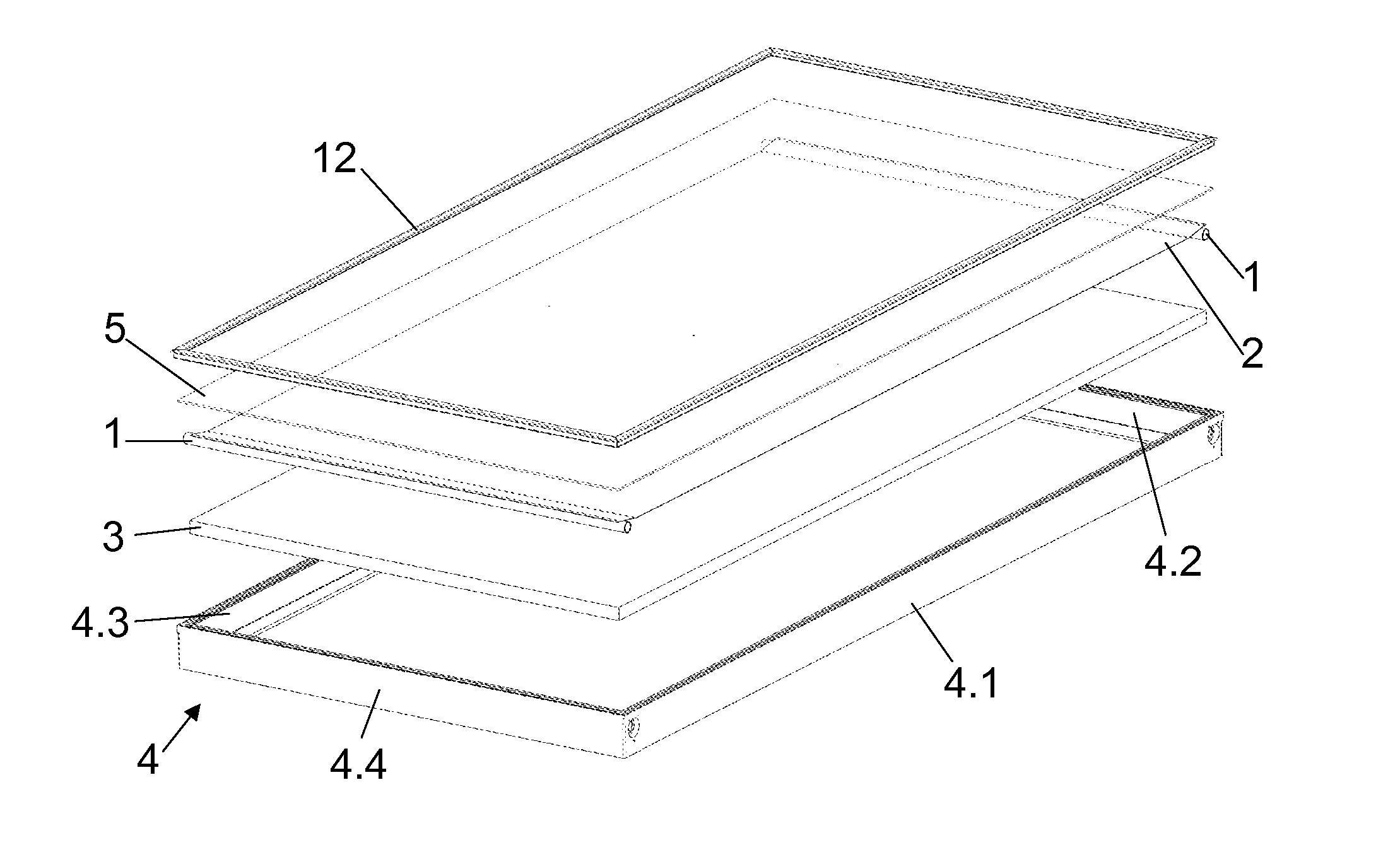
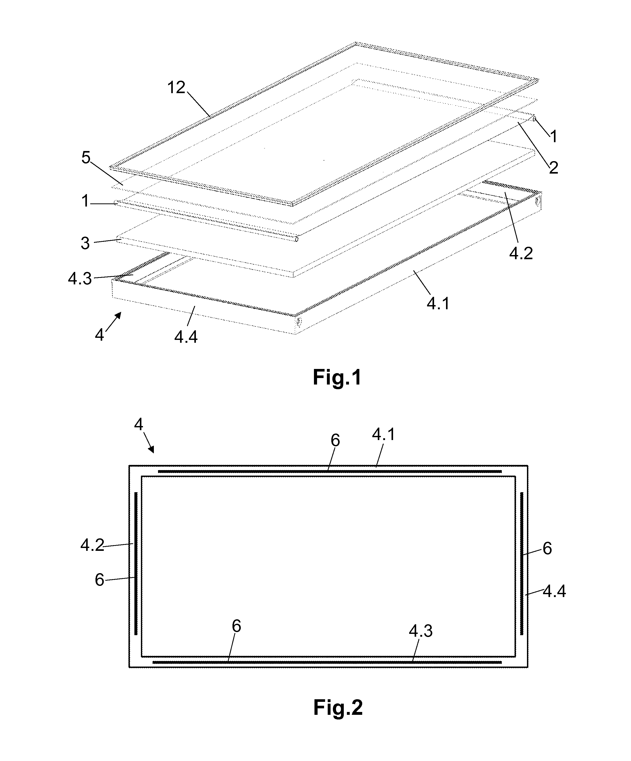
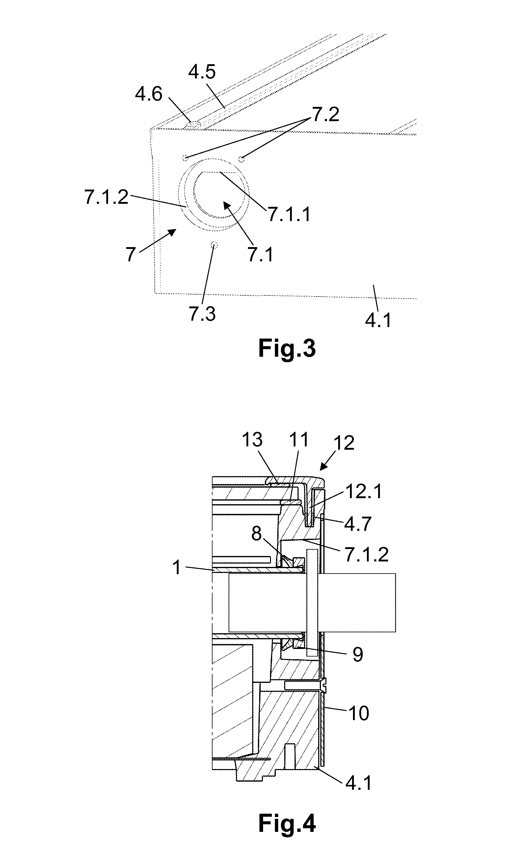
[0010]In view of the above, the present invention relates to a solar heat collector that comprises a pipe in which flows an energetic fluid, an absorbent plate in contact with said pipe, an insulation arranged in parallel to said absorbent plate and located on the side of the pipe opposite to said plate such that it exerts a constant force on it, a structure made of a plastic material with a parallelepiped shape which houses the aforementioned components of the collector, and a transparent cover placed on one of the greater faces of said structure on the side of the absorbent plate, wherein the structure consists of a frame formed by the four lateral faces of the parallelepiped that leaves the greater faces of the same open and is formed by injection of plastic material; said frame is reinforced by metallic profiles encapsulated in the a...


PUM


Abstract

Solar heat collector with a pipe in which flows an energetic fluid and a structure consisting of a frame of plastic material with metallic profiles encapsulated during the injection of said plastic material, which allows establishing orifices therein, providing a robust and lightweight collector with few components and dimensionally stable.

Description

TECHNICAL FIELD OF THE INVENTION[0001]The present invention belongs to the field of harnessing solar heat, such as solar heat collectors, and specifically their component parts.[0002]The invention relates to a solar heat collector comprising a pipe in which flows an energetic fluid, and a structure formed by a frame of plastic material with metal profiles encapsulated during injection thereof, and which enables the inclusion of different functions such as thermal insulation, mechanical resistance, a light weight, and integration, thereby defining a robust and lightweight collector that has few components and is dimensionally stable.BACKGROUND OF THE INVENTION[0003]Solar heat collectors are known comprising a pipe in which flows an energetic fluid and which have a structure that includes a plastic material.[0004]Examples of such collectors can be found in patents DE2713628 with foam and locally positioned reinforcement fibers, CN101070999 and U.S. Pat. No. 4,098,265 with foam, WO2011...

Claims


Application Information

Patent Timeline
Patent Type & Authority Applications(United States)
IPC IPC(8): F24J2/26F24J2/51F24J2/50F24S10/75
CPCF24J2/26F24J2/51F24J2/50Y02E10/44F24S2080/09F24S40/80F24S80/70F24S2025/601F24S2025/6012F24S80/453F24S80/457F24S40/42F24S80/45F24S80/50F24S10/75F24S80/60F24S80/58
Inventor SASTRE, CARLOS ALONSOPINILLA, ALBERTO ZAMARRONSENOVILLA, JUAN CARLOS MERINO
Owner FUNDACION CIDAUT
Why Eureka
Try Eureka