Rotary base for securing tools to a work table

a technology of securing tools and work tables, applied in the field of manufacturing, can solve the problems of screwing and securing tools, affecting the rotational angle of tools to change the position of tools, and affecting the quality of tools, and affecting the quality of tools. , to achieve the effect of reducing the risk of tool loosening and requiring period maintenan

Active Publication Date: 2020-02-04
UNIVERSIDAD NACIONAL DE ITAPUA
View PDF21 Cites 0 Cited by
  • Summary
  • Abstract
  • Description
  • Claims
  • Application Information

AI Technical Summary

Benefits of technology

[0013]Preferably, the rotary base object of the present invention can have seal rings in different areas to ensure the water-tightness of the hydraulic fluid, preventing leaks and guaranteeing effective functioning over time. There may be seal rings for example on the exterior lateral surface of the base piston, between the lower cover and the support base, in the joint of the cylinder of the actuation plunger to the support base or on the exterior lateral surface of the actuation plunger.
[0016]The object of the present invention constitutes a rotary base for securing tools to a work table which provides 360° absolute freedom of rotation to the tool by means of rotation of the base, maintaining the horizontal rotational plane completely parallel to the work table or any other installation surface and has a hydraulic fastening actuated by a simple threaded knob or screw which requires minimal force by the operator and provides firm securing of the tool.

Problems solved by technology

It is known that the securing of presses and other tools to a work table involves physical force and in addition rotating these tools to change the position of the tool has limitations in rotational angles in the majority of the devices.
Alternatively, other solutions have mechanical fasteners by means of screws or jaws as is shown in document U.S. Pat. No. 1,901,120A which have the drawback that the screws and gripping and securing means, with use over time, end up loosening which involves period maintenance.

Method used


Image

  • Rotary base for securing tools to a work table

Examples


Embodiment Construction

[0007]The present invention solves the problems existing in the prior art by means of a rotary base for securing tools of any type to a work table.

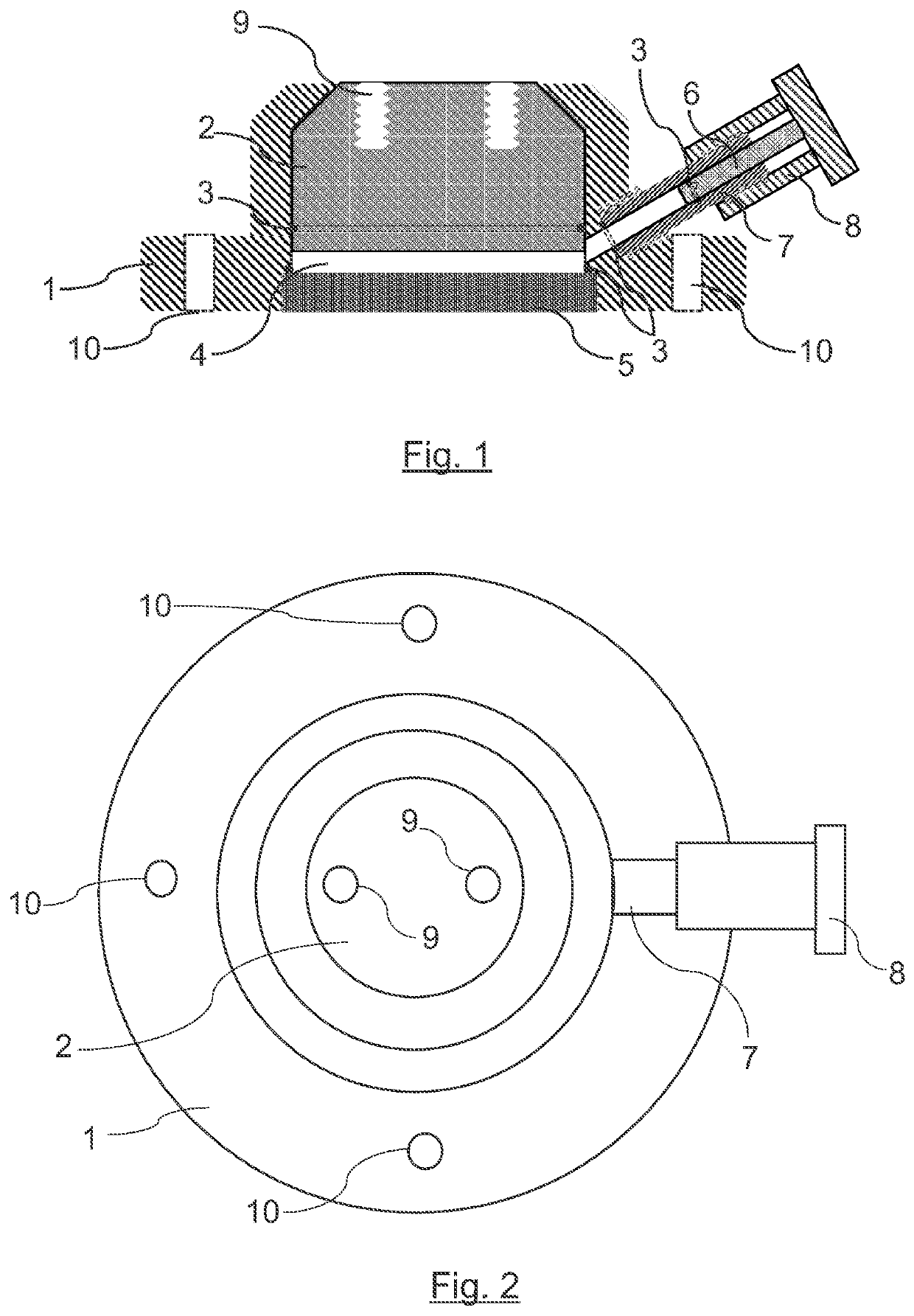
[0008]The proposed invention has a vertical cylindrical support base which has a truncated upper end, the support base being configured to be fixed to the work table. In the interior of said support base, and centric thereto, there is a threaded lower cover fixed to the interior of the support base and a cylindrical base piston and with a truncated upper end which has means to secure tools. The base piston is arranged on the threaded lower cover and is vertically displaced on this threaded lower cover through the interior of the support base, actuated by a lifting system. The displacement carried out by the base piston is between a lower unlocking position, in which the base piston rotates freely around its axis with respect to the support base, and an upper locking position, in which the rotation of the base piston with respect to the su...


PUM


Abstract

Rotary base for securing tools to a work table with a cylindrical support base and truncated upper end, in whose interior and concentric thereto, there is a threaded lower cover and a cylindrical base piston and with a truncated upper end with means to secure tools. The base piston is arranged on the threaded lower cover and is vertically displaced on this threaded lower cover through the interior of the support base, actuated by a lifting system between a lower unlocking position in which the base piston rotates freely around its axis with respect to the support base and an upper locking position in which the rotation of the base piston with respect to the support base is locked by means of friction of its truncated upper end against the truncated upper end of the support base.

Description

CROSS REFERENCE TO RELATED APPLICATION[0001]This application claims priority of Paraguay Application No. P 1842735 PY filed Jun. 5, 2018, application which is incorporated herein by reference.FIELD OF THE INVENTION[0002]The present invention belongs to the technical field of manufacturing, specifically to the machining of pieces, and more specifically to the means for fixing various tools, such as presses, lathes, drills, mills, cutting tools, tightening tools, etc., to a work table. The invention relates in particular to a rotary base for securing tools to a work table which allows the rotation of the tool to reach different positions. Said rotary base therefore has an unlocking position in which a base piston, on which the tool is fixed, rotates freely around its axis and a locking position in which the rotation of the base piston is locked by friction of said base piston on a support.BACKGROUND OF THE INVENTION[0003]It is known that the securing of presses and other tools to a wo...

Claims


Application Information

Patent Timeline
Patent Type & Authority Patents(United States)
IPC IPC(8): B23Q3/02B23Q1/26
CPCB23Q1/26B23Q3/02B23Q1/0054B23Q1/52
Inventor CANO COSCIA, EUGENIO JOSEPRENDESKI STOLARUK, CINTHIA TATIANACUADRA FENSTERSEIFER, VALERIA MARIA ELIZABETHLISCHUK BARAN, JULIAN MARCELO
Owner UNIVERSIDAD NACIONAL DE ITAPUA
Why Eureka
Try Eureka