Back-Contact Electron Reflectors Enhancing Thin Film Solar Cell Efficiency

a technology of back-contact electron reflectors and solar cells, which is applied in the direction of electrical apparatus, semiconductor/solid-state device manufacturing, and semiconductor devices, etc., can solve the problems of limited solar cell efficiency advances, lack of clear solutions, and ineffective current methods of inserting optical reflectors within thin-film solar cells to fully provide continuous solar cell efficiency improvement. , to achieve the effect of improving the efficiency of solar cells,

Inactive Publication Date: 2014-06-19
INTERMOLECULAR
View PDF13 Cites 22 Cited by
  • Summary
  • Abstract
  • Description
  • Claims
  • Application Information

AI Technical Summary

Problems solved by technology

Unfortunately, conventional approaches to each method have provided limited advances in solar cell efficiency.
Although these methods are currently being pursued to achieve higher thin film solar cell efficiencies, there are no clear solutions due to technology limitations in current research and design (R&D).
However, current methods of inserting optical reflectors within thin film solar cells may not be effective to fully provide continuous solar cell efficiency improvement.

Method used


Image

  • Back-Contact Electron Reflectors Enhancing Thin Film Solar Cell Efficiency
  • Back-Contact Electron Reflectors Enhancing Thin Film Solar Cell Efficiency
  • Back-Contact Electron Reflectors Enhancing Thin Film Solar Cell Efficiency

Examples


Embodiment Construction

[0023]A detailed description of one or more embodiments is provided below along with accompanying figures. The detailed description is provided in connection with such embodiments, but is not limited to any particular example. The scope is limited only by the claims and numerous alternatives, modifications, and equivalents are encompassed. Numerous specific details are set forth in the following description in order to provide a thorough understanding. These details are provided for the purpose of example and the described techniques may be practiced according to the claims without some or all of these specific details. For the purpose of clarity, technical material that is known in the technical fields related to some embodiments have not been described in detail to avoid unnecessarily obscuring the description.

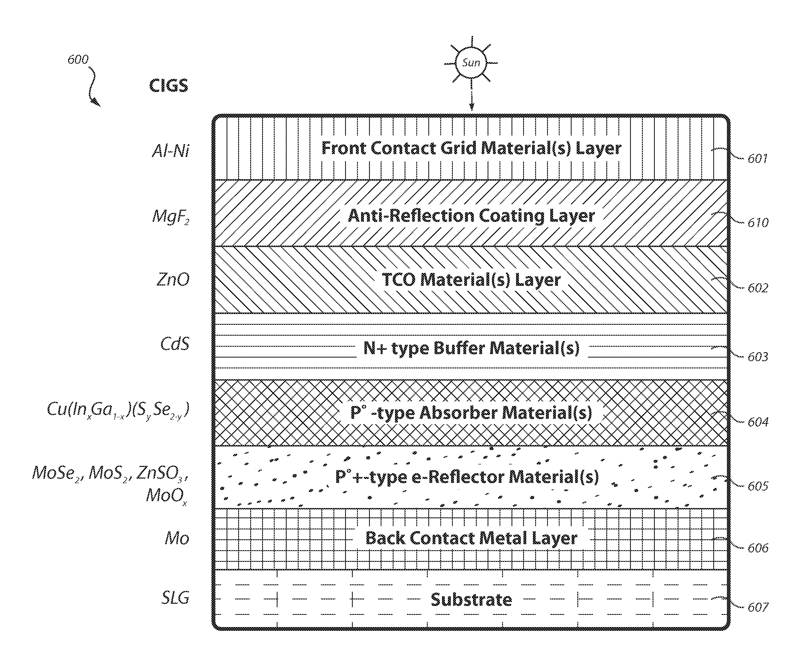
[0024]Methods for improving the efficiency of solar cells are disclosed. A solar cell consistent with the present disclosure includes a back contact metal layer disposed on ...


PUM


Abstract

Methods for improving the efficiency of solar cells are disclosed. A solar cell consistent with the present disclosure includes a back contact metal layer disposed on a substrate. The solar cell also includes an electron reflector material(s) layer formed on the back contact metal layer and an absorber material(s) layer disposed on the electron reflector material(s) layer. In addition, the solar cell includes a buffer material(s) layer formed on the absorber material(s) layer wherein the electron reflector material(s) layer, absorber material(s) layer, and buffer material(s) layer form a pn junction within the solar cell. Furthermore, a TCO material(s) layer is formed on the buffer material(s) layer. In addition, the front contact layer is formed on the TCO material(s) layer.

Description

FIELD[0001]The present disclosure relates to enhancing thin film solar cell efficiency.BACKGROUND[0002]A conventional solar cell typically includes a light absorbing material(s) layer connected to an external circuit. Charge carriers are generated in the light absorber material(s) by absorbing photons of light therein which are subsequently driven towards one or more contacts within the cells. Advantageously, the charge establishes a photovoltage at open circuit (Voc) and generates a photocurrent at short circuit. As such, when a load is connected to an external circuit, the solar cell can produce current and voltage to do electrical work.[0003]Much research has been given to increasing the efficiency of solar cells. Solar cell efficiency is an important metric because it is an indirect measurement of the amount of power that can be generated from a solar cell. Two primary physical mechanisms have been considered to achieve high thin-film solar cell efficiency: (1) using p-type abso...

Claims


Application Information

Patent Timeline
Patent Type & Authority Applications(United States)
IPC IPC(8): H01L31/0264H01L31/18
CPCH01L31/18H01L31/0264H01L31/0322H01L31/03923H01L31/0749H01L31/056Y02E10/52Y02E10/541
Inventor LEE, MANKOOBARABASH, SERGEYCHIANG, TONY P.PRAMANIK, DIPANKAR
Owner INTERMOLECULAR
Why Eureka
Try Eureka