Modular double adjustable chock

a double adjustable, chock technology, applied in the direction of machine supports, domestic objects, applications, etc., can solve the problems of unfavorable bolt shank support, unattractive business aspect, and relatively expensive mechanical components in the middle element, so as to accurately control the mechanical strength of the center stud engagement, and reduce the cost of machining operation

Inactive Publication Date: 2014-06-19
SKF BV
View PDF20 Cites 5 Cited by
  • Summary
  • Abstract
  • Description
  • Claims
  • Application Information

AI Technical Summary

Benefits of technology

[0012]The inventor proposes a more attractive solution. An aspect of the solution resides in replacing the known intermediate element of the known adjustable chock by two separate components: a center element accommodating the rotationally symmetrical intermediate surface, and a separate center stud that serves as the hollow shaft. The center stud basically consists of a threaded hollow rod. In other words, it has an externally threaded cylindrical surface with a diameter that defines the maximum diameter of the centre stud. The external screw thread of the centre stud engages with a complementary inner screw thread of the center element. As a result, the same center element and the same second element can be combined with externally threaded center studs of different lengths so as to create different adjustable chocks suitable for different ranges of height. Externally threaded center studs of different lengths can be simply made by cutting off pieces of different lengths of a threaded hollow rod. A threaded hollow rod is a relatively inexpensive comp

Problems solved by technology

The intermediate element is a relatively expensive mechanical component to make owing to, among other things, the machining operations required.
This is an unattractive aspect of the business, if only from the perspective of costs.
If the second through-hole of the

Method used


Image

  • Modular double adjustable chock
  • Modular double adjustable chock
  • Modular double adjustable chock

Examples


Embodiment Construction

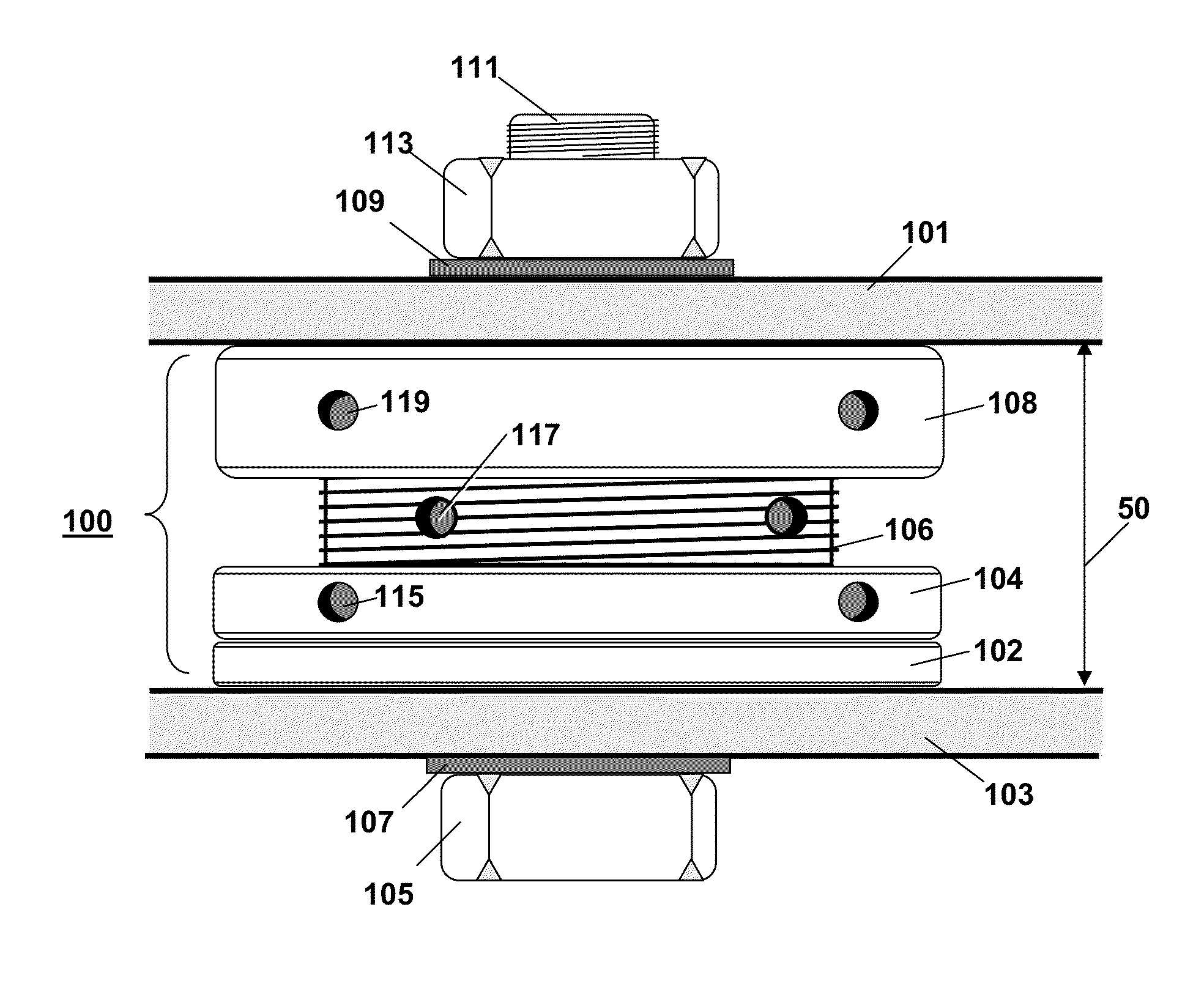
[0027]The invention relates to a system designed for use as an adjustable chock for connecting machinery to a support along an axis of the adjustable chock. The system may be made commercially available as an assembled entity of as a kit-of-parts.

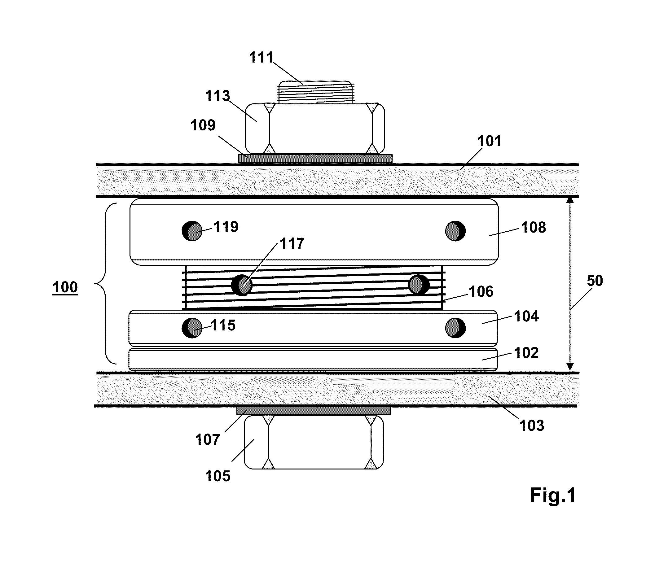
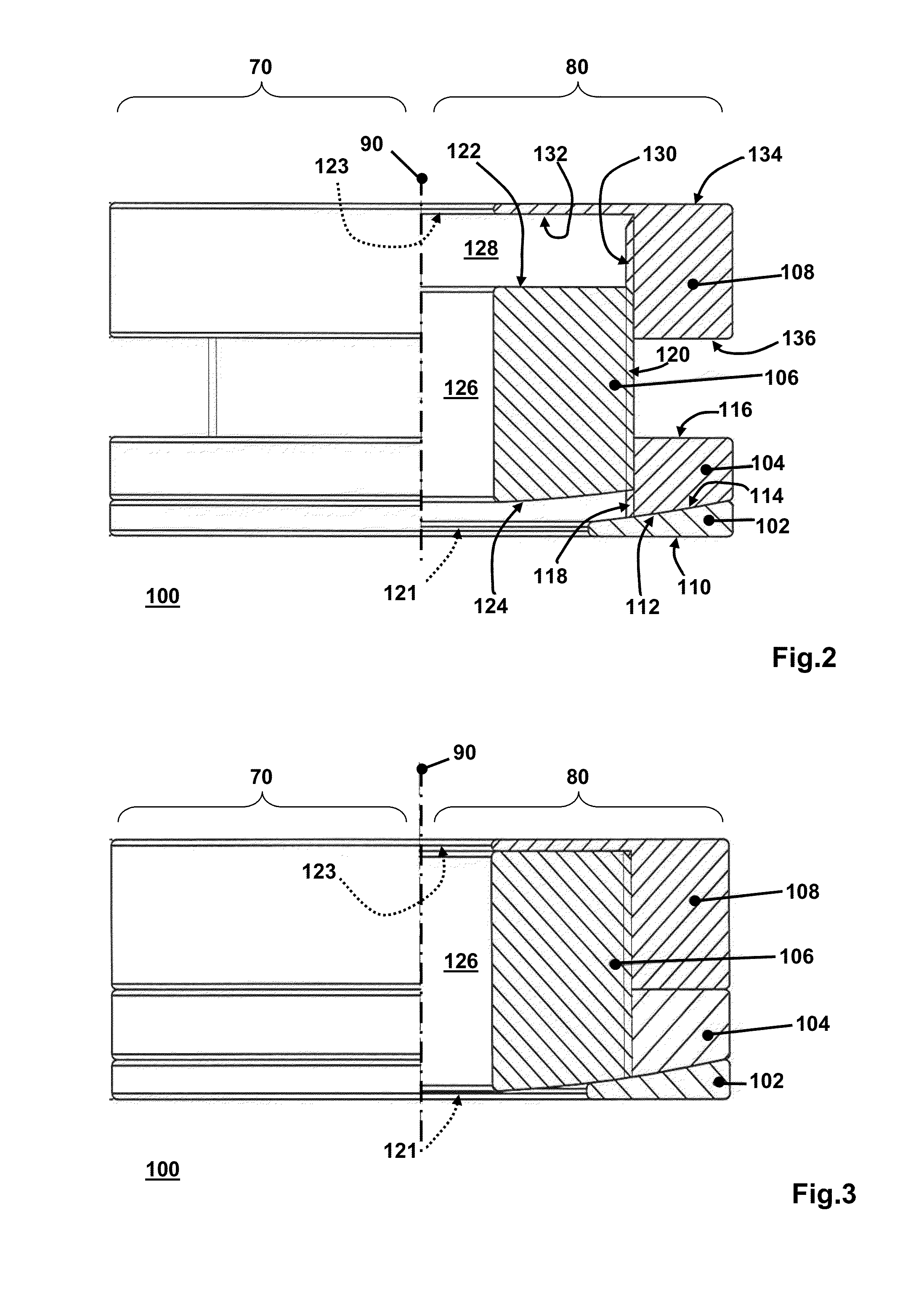
[0028]FIGS. 1, 2 and 3 are diagrams of a first adjustable chock 100 according to the invention. The first adjustable chock 100 is of a modular design and comprises a first element 102, a second element 108, a center element 104, and a center stud 106. In operational use of the chock 100, the first element engages with a piece of machinery 101 and the second element engages with a support 103. The first element 102 and the center element 104 have complementarily shaped contact surfaces to allow for lateral adjustment of the first element 102 relative to the second element 108. The center stud 106 is connected to the center element 104 through a screwed connection. The center stud 106 is connected to the second element 108 through another scr...


PUM


Abstract

An adjustable chock (100) of a modular design comprises a first element (102), a second element (108), a center element (104), and a center stud (106). In operational use of the chock, the first element engages with a piece of machinery (101) and the second element engages with a support (103). The first element (102) and the center element (106) have complementarily shaped contact surfaces to allow for lateral adjustment of the first element relative to the second element. The center stud (106) is connected to the center element (104) through a screwed connection. The center stud (106) is connected to the second element (108) through another screwed connection. The modular design allows using the same first element (102), the same second element (108) and the same center element (104) with center studs of different lengths.

Description

FIELD OF THE INVENTION[0001]The invention relates to a system designed for use as an adjustable chock for connecting a piece of machinery to a support. The invention also relates to a further system comprising machinery mounted on a support via an adjustable chock.BACKGROUND ART[0002]Adjustable chocks are known in the art. See, for example, U.S. Pat. No. 7,438,274, issued to René Vermeulen for “Adjustable foot for setting up equipment in alignment” and incorporated herein by reference, and U.S. Pat. No. 6,068,234 (corresponds to WO97 / 35144), issued to Elbert Keus for “Setting foot provided with sealing means”, and incorporated herein by reference.[0003]Each of the adjustable chock of U.S. Pat. No. 7,438,274 and the adjustable chock of U.S. Pat. No. 6,068,234 is referred to herein below as the known adjustable chock. The known adjustable chock comprises a first element, an intermediate element and a second element.[0004]The first element has a rotationally symmetrical first surface t...

Claims


Application Information

Patent Timeline
IPC IPC(8): F16M7/00
CPCF16M7/00
Inventor HOOGHART, BAMVERMEULEN, RENEVOGELAAR, DICK
Owner SKF BV
Why Eureka
Try Eureka