
Air spring piston for a heavy-duty vehicle

a technology for air springs and heavy-duty vehicles, which is applied in the direction of shock absorbers, mechanical equipment, transportation and packaging, etc., can solve the problems of reducing the optimal ride characteristics of the axle/suspension system, affecting and reducing the practicability of piston manufacturing from composite materials, etc., to achieve the effect of improving the damping of the air spring

Inactive Publication Date: 2014-06-19
CONTITECH LUFTFEDERSYST +1
View PDF10 Cites 32 Cited by
  • Summary
  • Abstract
  • Description
  • Claims
  • Application Information

AI Technical Summary

Benefits of technology

The present invention provides a piston for an air spring in a heavy-duty vehicle that improves the damping of the air spring during operation of the vehicle.

Problems solved by technology

It is also desirable to dampen the vibrations or oscillations that result from such forces in order to reduce wheel and / or suspension bounce, which in turn can potentially harm the wheels and the components of the axle / suspension system, thereby reducing optimal ride characteristics of the axle / suspension system.
Because the prior art air spring piston described above may have a relatively complex multi-piece structural design, manufacture of the piston from composite materials is not feasible.
Moreover, prior art composite air spring piston designs of the enclosed volume variety generally do not provide sufficient bumper force support to optimally react bumper forces during operation of the air spring, which can potentially lead to failure of the air spring piston and or components of the axle / suspension system.
Furthermore, some prior art air spring piston designs do not provide damping characteristics so that the use of a shock absorber is required to provide damping to the axle / suspension system.

Method used


Image

  • Air spring piston for a heavy-duty vehicle
  • Air spring piston for a heavy-duty vehicle
  • Air spring piston for a heavy-duty vehicle

Examples


Embodiment Construction

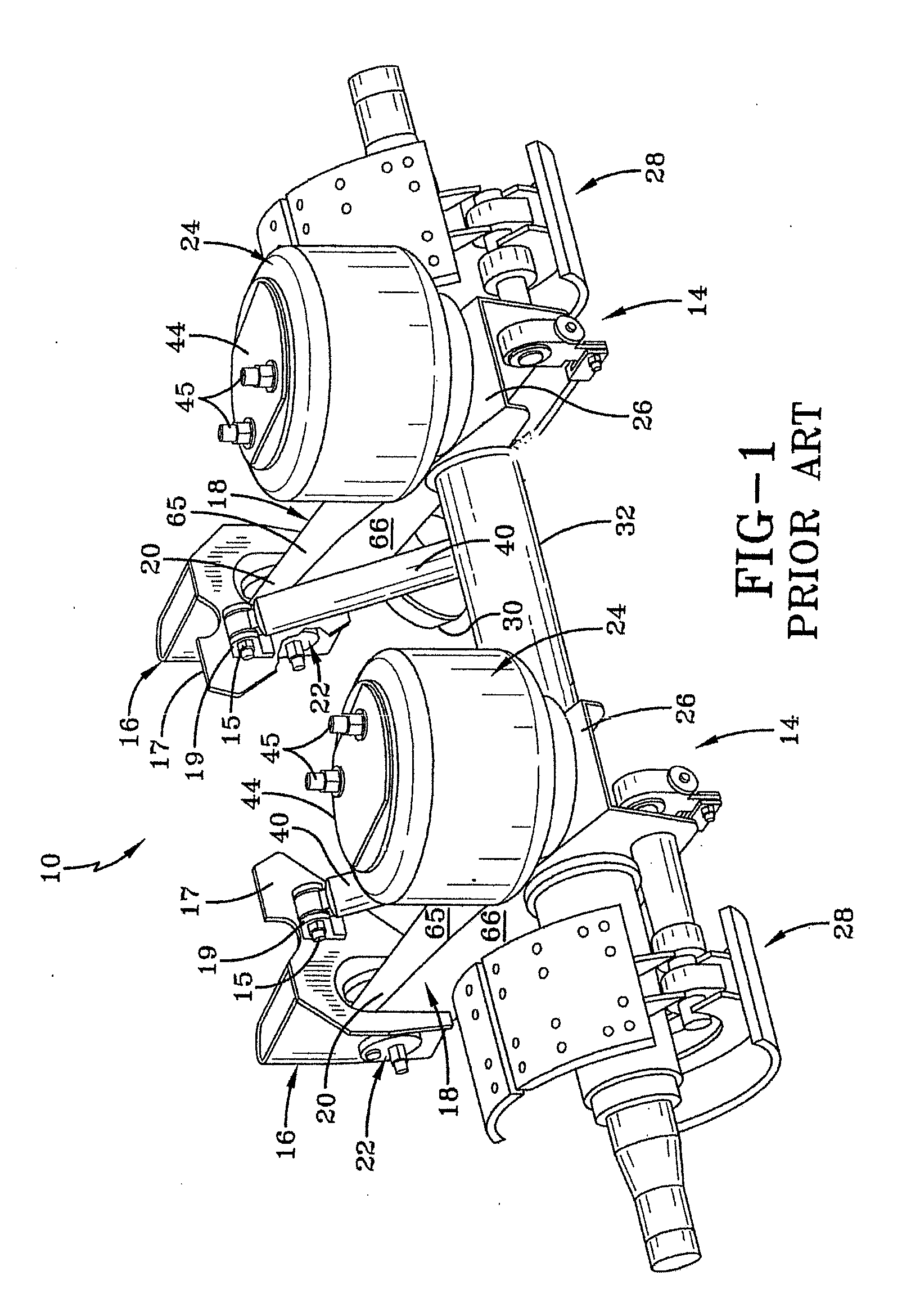
[0034]In order to better understand the environment in which the air spring piston for heavy-duty vehicles of the present invention is utilized, a trailing arm overslung beam-type air-ride axle / suspension system that incorporates a prior art heavy-duty vehicle trailer air spring 24, is indicated generally at 10, is shown in FIG. 1, and now will be described in detail below.

[0035]It should be noted that axle / suspension system 10 is typically mounted on a pair of longitudinally-extending spaced-apart main members (not shown) of a heavy-duty vehicle, which is generally representative of various types of frames used for heavy-duty vehicles, including primary frames that do not support a subframe and primary frames and / or floor structures that do support a subframe. For primary frames and / or floor structures that do support a subframe, the subframe can be non-movable or movable, the latter being commonly referred to as a slider box. Because axle / suspension system 10 generally includes an...


PUM


Abstract

An air spring piston for a heavy-duty vehicle includes a top portion and a bottom portion. The top portion includes a bumper and a connecting means for an air spring bellows. The bottom portion is mounted on a structure of the vehicle. The top portion and bottom portion are connected to each other to form a piston chamber and include a bearing means for reacting bumper forces from the bumper to the bottom portion and to the structure of the vehicle on which the bottom portion is mounted. The piston chamber is in fluid communication with a bellows chamber of the air spring via an opening, wherein the geometry of the opening is such that during dynamic spring movements, the pressure in the piston chamber and the pressure in the bellows chamber are not equalized.

Description

CROSS-REFERENCE TO RELATED APPLICATION[0001]This application claims the benefit of U.S. Provisional Patent Application Ser. No. 61 / 736,593, filed Dec. 13, 2012.BACKGROUND OF THE INVENTION[0002]1. Field of the Invention[0003]The invention relates generally to the art of axle / suspension systems for heavy-duty vehicles. More particularly, the invention relates to air-ride axle / suspension systems for heavy-duty vehicles, which utilize an air spring to cushion the ride of the vehicle. More specifically, the invention is directed to a piston for an air spring of a heavy-duty vehicle air-ride axle / suspension system, in which the air spring piston is formed of at least two parts, an upper portion and a lower portion, that cooperate with one another to form an enclosed piston chamber volume. Both the upper portion and the lower portion of the air spring piston include a bearing means to react bump forces from the bumper situated on the upper portion of the air spring piston to the mounting a...

Claims


Application Information

Patent Timeline
Patent Type & Authority Applications(United States)
IPC IPC(8): F16F9/05F16F9/32
CPCB60G2202/152B60G2204/4502B60G2206/424B60G2206/82013B60G9/003B60G11/28B60G2206/7101B60G2300/026F16F9/057
Inventor RAMSEY, JOHN E.LONG, THOMAS J.ANDERSON, BRIAN R.HANSEN, CARSTENMERSHON, MOHAMAD TAGHIZADEHRICHARDSON, GREGORY A.FERNANDEZ, ARMANDO VAZQUEZ
Owner CONTITECH LUFTFEDERSYST
Features
  • Generate Ideas
  • Intellectual Property
  • Life Sciences
  • Materials
  • Tech Scout
  • Unparalleled Data Quality
  • Higher Quality Content
  • 60% Fewer Hallucinations
Learn More