Device for thermal monitoring of the terminals of an electrical connection device

a technology for electrical connection devices and terminals, applied in the direction of coupling device details, coupling device connections, emergency protective circuit arrangements, etc., can solve the problems of abnormal overheating, affecting the quality of the contact surface, and affecting the normal temperature rise of the connection devi

Inactive Publication Date: 2014-06-19
CHARLES
View PDF1 Cites 16 Cited by
  • Summary
  • Abstract
  • Description
  • Claims
  • Application Information

AI Technical Summary

Benefits of technology

[0035]It is another advantage of this invention to provide a means prohibit short-circuiting of the monitored terminals by one or more fault trigger elements, and limits or modulates the fault current value sent to the protective conductor.

Problems solved by technology

However, the abnormal temperature rise of these connecting devices often occurs over time.
These abnormal overheating originate from the gradual increase in electrical resistance connections that can oppose the passage of current, promoting the aging of the device connection.
For example, slight oxidation of copper (bare and exposed at the connection) will cause a decrease in the quality of the contact surface and a modification of the constriction of the electric lines, but also a slight but inevitable Joule effect heating.
Experts have identified these abnormal heating as the main cause of electrical fires.
Once the ideal conditions for igniting a fire are in place, heating alone, a spark, or an arc can cause ignition if a fuel material and a combustive are present, which usually ends up being the case because the environment is deteriorating.
The risk of fire is much more widespread that this can occur even at a connection of a circuit with low electric power.
Connections and connection devices therefore have inherently dangerous overheating risks.
Firstly, a primary risk factor is related to the number of connections since we make hundreds of connections to make, for example, an electrical system for a house.
Human factor is also important: A small error in the implementation or modification of the installation will ultimately lead to premature aging of the connector and fire.
Connecting devices also suffer from all kinds of stress that may increase the risk of heat: Surges, electromagnetic forces, vibrations, possible traction forces if the fasteners are inadequate.
Finally, for many connecting devices scattered in buildings, the verification of connections is impractical.
However, the known protection devices do not physically detect abnormal hotspot heating of electrical connection that may create the ideal conditions for igniting a fire.
According to a prior art solution to monitor abnormal heating of an electrical connection, periodic inspections are carried out with infrared cameras to identify potential hotpots in electrical installation and prevent the ideal conditions for igniting a fire.
Also, such a periodic inspection is long to implement or unfeasible in certain cases.
However, the device disclosed in FR-2,803,122 does not allow to simultaneously monitor a plurality of electric connection terminals, including terminals and a connection device comprising an active terminal, a terminal and a Neutral terminal protection.

Method used


Image

  • Device for thermal monitoring of the terminals of an electrical connection device
  • Device for thermal monitoring of the terminals of an electrical connection device
  • Device for thermal monitoring of the terminals of an electrical connection device

Examples


Embodiment Construction

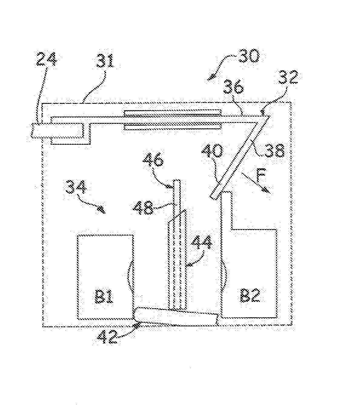
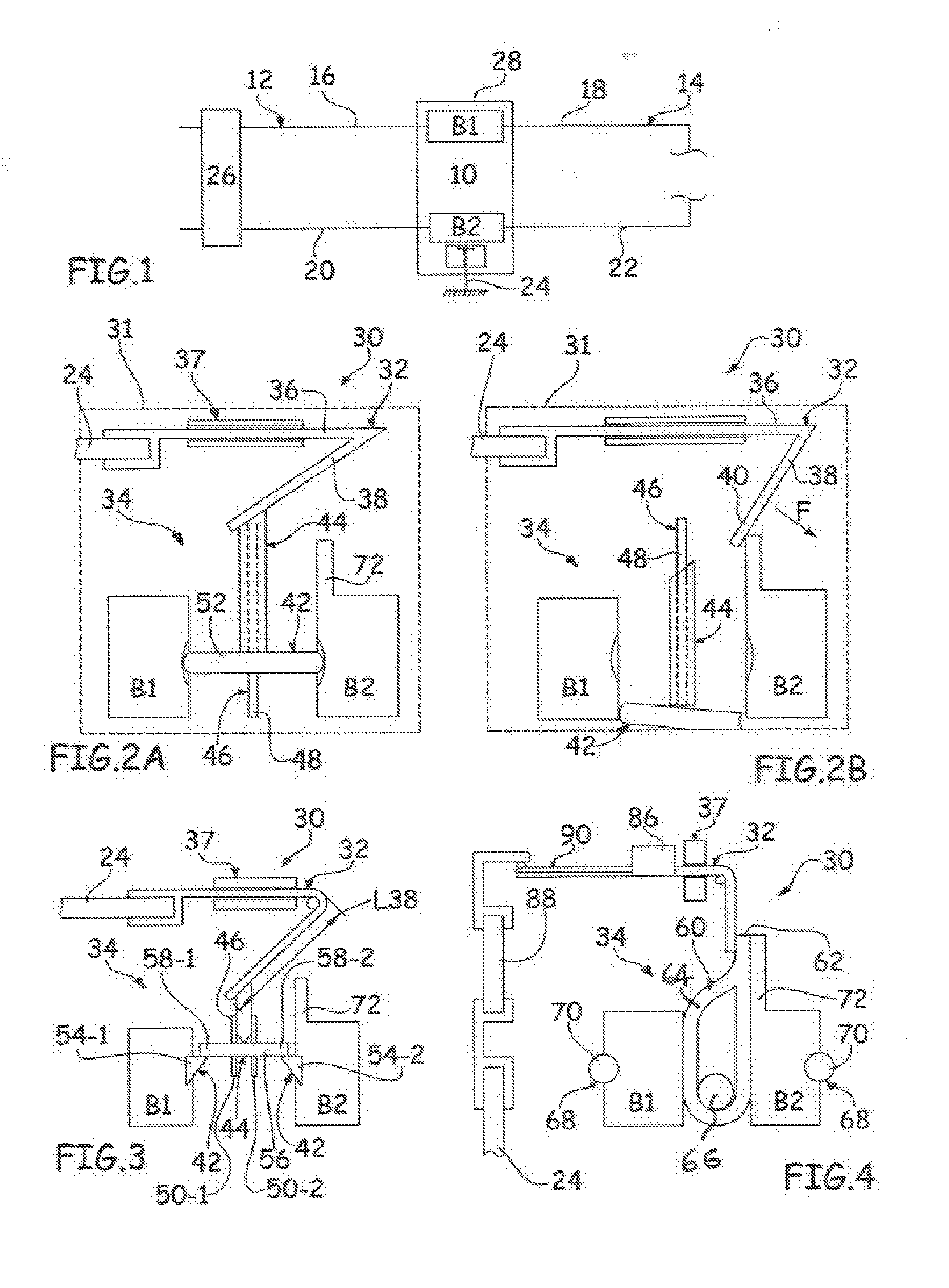
[0054]A thermal monitoring device according to the invention is intended to equip an electrical connection device 10 as shown in FIG. 1 and connecting a first electrical circuit 12 to a second electrical circuit 14.

[0055]For example, the first circuit 12 may be a circuit of an electrical distribution system and the second circuit 14 may be the internal circuit of an electrical appliance powered by the distribution circuit.

[0056]To connect the first circuit 12 to second circuit 14, the electrical connection device 10 comprises at least two monitor terminals: a first terminal B1 for connecting a first conductor 16 of the first circuit 12 to a first conductor 18 of the second circuit 14, and a second terminal B2 allows for connecting a second conductor 20 of the first circuit 12 to a second conductor 22 of the second circuit 14.

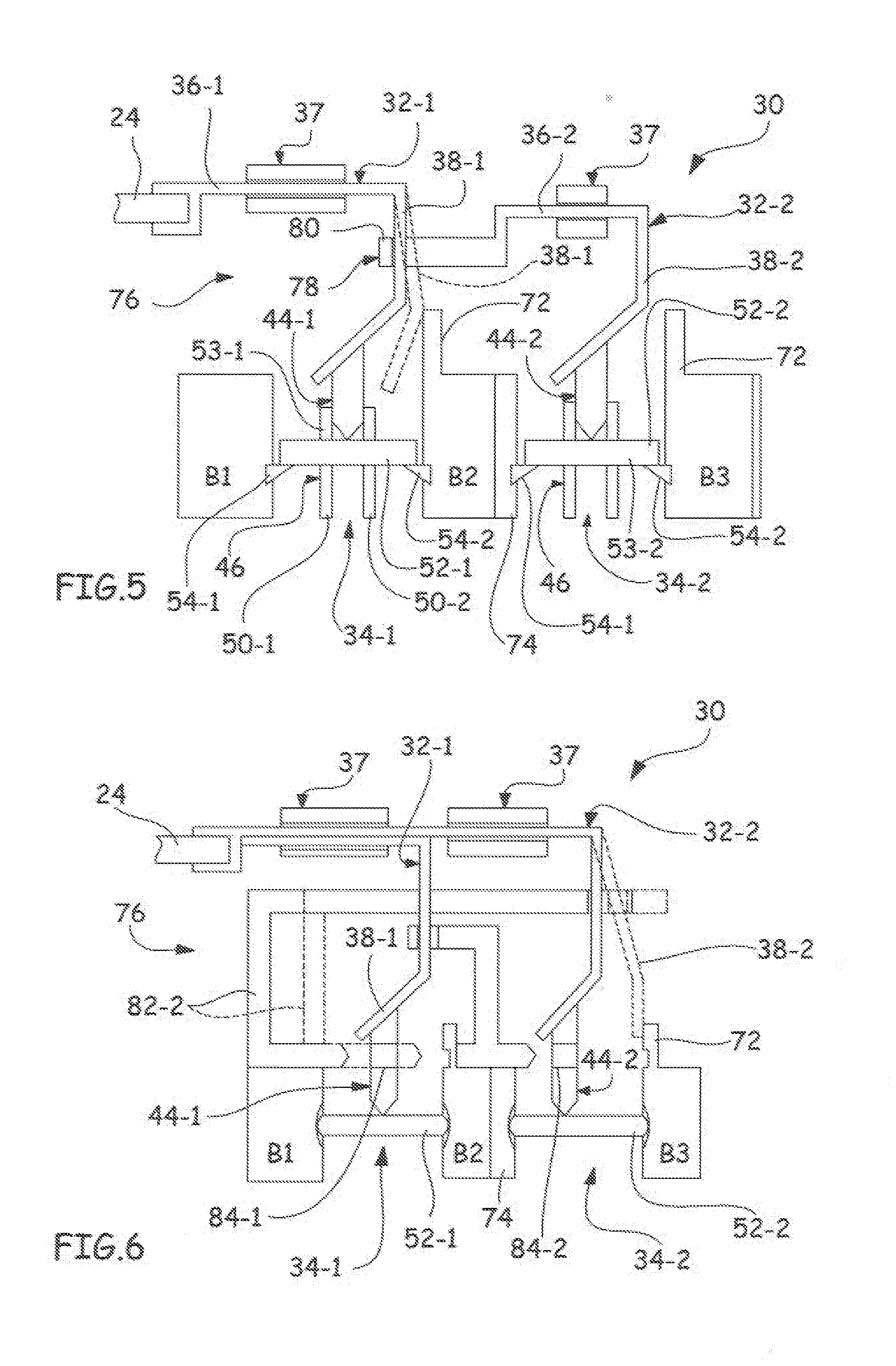
[0057]According to the single-phase, two-phase or three-phase electrical installation, the electrical connection device 10 may monitor: one, two, or three activ...


PUM


Abstract

The subject matter of the invention is a device for thermal monitoring of a connection device, said connection device comprising at least two terminals to be monitored, including at least one active terminal, the device comprising at least one electrically conductive fault-initiating element electrically connected to a protective conductor, and electrically insulating detection means for detecting abnormal heating, in thermal contact with each terminal to be monitored, the detection means preventing each fault-initiating element from coming into electrical contact with an active terminal so long as these detection means are not subject to a threshold temperature, and the detection means releasing the fault-initiating element when they are subject to a temperature higher than or equal to the threshold temperature in such a way that this fault-initiating element comes into electrical contact with an active terminal, the thermal monitoring device being characterized in that each fault-initiating element comprises a fixed part and a part that can be moved between a “no fault” position, in which it is held at a distance from an active terminal by the detection means, and a “fault” position in which it is released by the detection means and comes into electrical contact with an active terminal.

Description

[0001]This application claims priority based on PCT / FR2012 / 051882 filed Aug. 18, 2011FIELD OF THE INVENTION[0002]The present invention relates generally to electrical devices but more specifically to the thermal monitoring of the terminals of an electrical connection device.BACKGROUND OF THE INVENTION[0003]There are many connection devices permit connecting the leads permanently together, in an electrical installation or in an electric appliance. Connection devices moat visible used to connect the leads of the installation with connection devices such as plugs or cable outlets, switches, light sockets, 10 etc.[0004]There are also different types of connecting devices in electrical equipment such as extension cords or power strips, and more generally in all appliances and industrial devices.[0005]Whatever their use, these connecting devices are subject to consistent standards both in terms of their quality and for their implementation. However, the abnormal temperature rise of these ...

Claims


Application Information

Patent Timeline
Patent Type & Authority Applications(United States)
IPC IPC(8): H02H5/04
CPCH01H37/767H01R13/7137H02H5/047
Inventor CHARLES, CYRIL
Owner CHARLES
Why Eureka
Try Eureka