Image forming apparatus

a technology of image forming apparatus and photosensitive drum, which is applied in the direction of electrographic process apparatus, corona discharge, instruments, etc., can solve the problems of affecting the operation of the electrographic unit, the electric discharge between the photosensitive drum and the charging unit may become larger, and the surface potential of the photosensitive drum is liable to fluctuate, so as to suppress the deterioration of the photosensitive drum and suppress the uneven density of halftones

Active Publication Date: 2014-06-19
CANON KK
View PDF3 Cites 4 Cited by
  • Summary
  • Abstract
  • Description
  • Claims
  • Application Information

AI Technical Summary

Benefits of technology

[0009]In order to solve the above-mentioned problem, the present application provides an image forming apparatus which can suppress halftone uneven density due to transfer memory and still can suppress deterioration of a photosensitive drum.

Problems solved by technology

In this case, transfer of charge from the transfer member to the photosensitive drum may cause fluctuations in a surface potential of the photosensitive drum.
In particular, when the recording material is not introduced to the transfer portion, charge is liable to be transferred from the transfer member to the photosensitive drum, and thus, fluctuations in surface potential of the photosensitive drum are liable to occur.
Such a surface potential difference (transfer memory) on the photosensitive drum after the image-receiving member passes through the transfer portion may remain after the photosensitive drum is recharged by a charging unit, which is a cause of uneven density of a halftone image.
However, with regard to the means disclosed in Japanese Patent Application Laid-Open No. 2008-8991, the photosensitive drum is charged to a potential which is higher than that necessary for image formation, and thus, electric discharge between the photosensitive drum and the charging unit may become larger and deterioration of the photosensitive drum may be accelerated.
Further, a potential necessary for image formation is formed by exposing the photosensitive drum to light to a small extent, and thus, the exposure may also accelerate the deterioration of the photosensitive drum.

Method used


Image

  • Image forming apparatus
  • Image forming apparatus
  • Image forming apparatus

Examples


embodiment 1

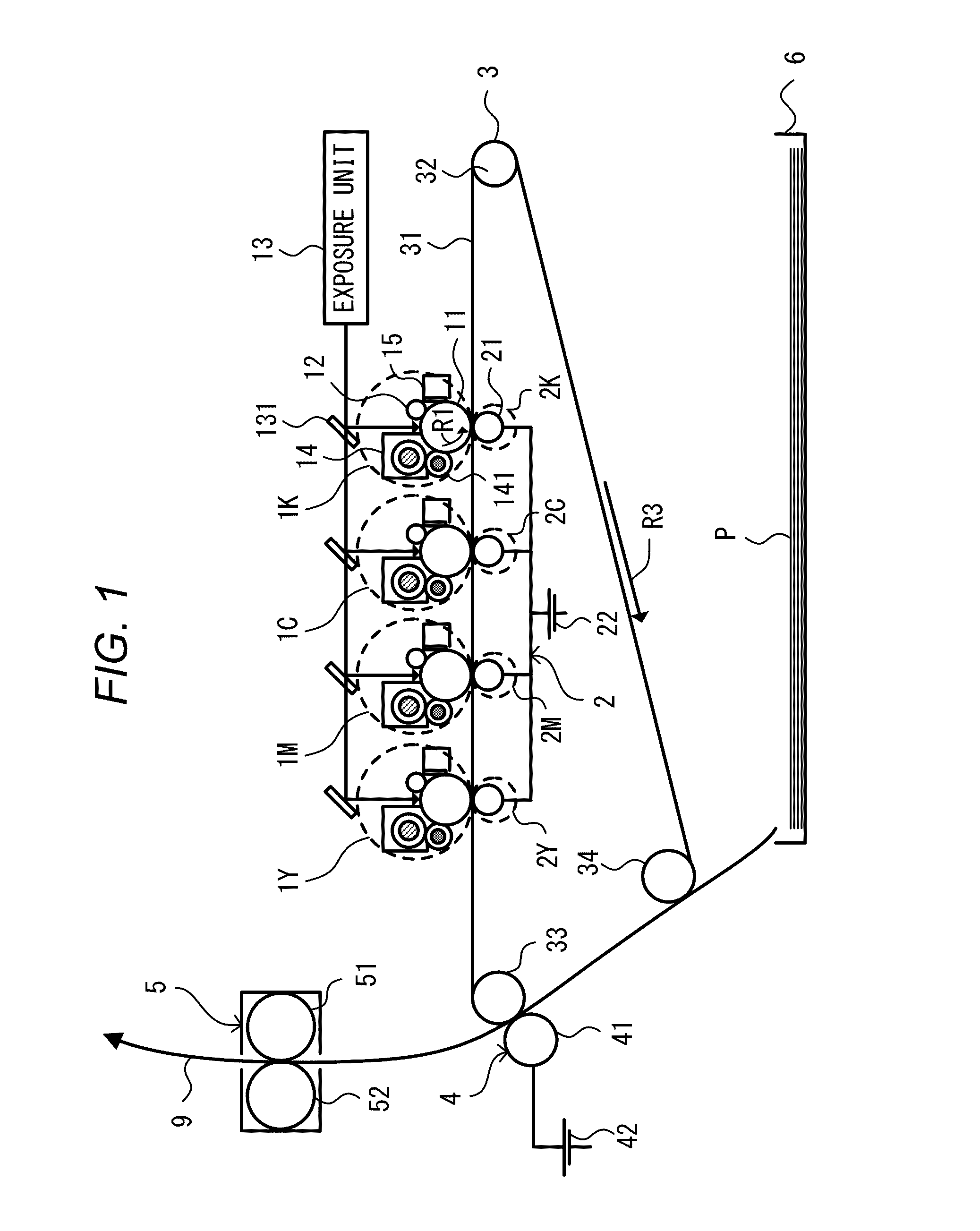
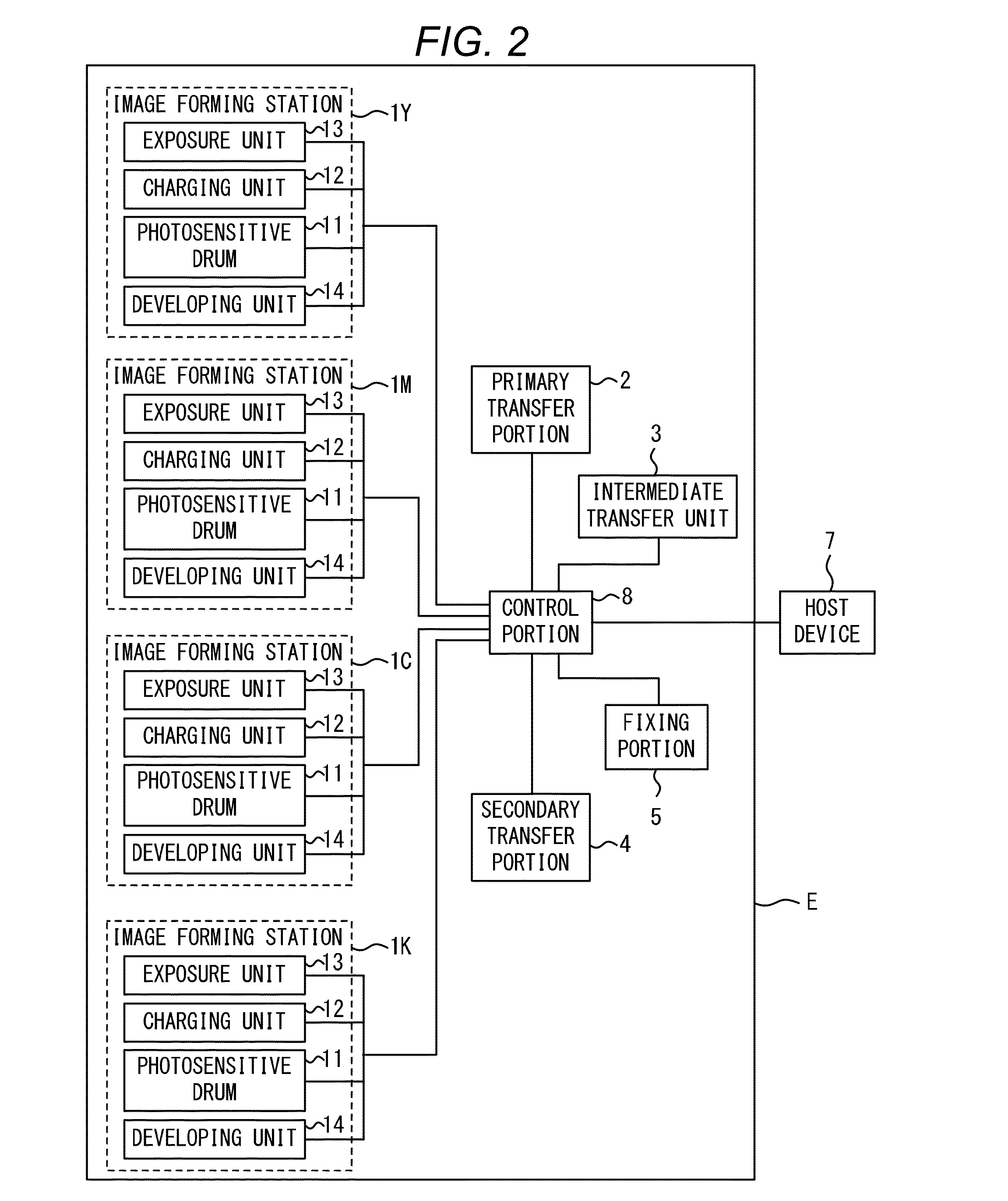
[0024]An image forming apparatus according to Embodiment 1 of the present invention will be described. The image forming apparatus according to the embodiment is a full-color image forming apparatus of four colors, i.e., yellow, magenta, cyan, and black, which uses an electrophotographic process and has a resolution of 600 dpi. The image forming apparatus forms an image on a sheet-shaped recording material P as a recording medium based on electrical image signals which are input from a host device such as an image reader, a personal computer, or a facsimile machine to a control portion. The control portion exchanges various kinds of electrical information with the host device, and exercises centralized control over image forming operation of the image forming apparatus in accordance with a predetermined control program or a lookup table.

[0025]FIG. 1 illustrates a schematic structure of the image forming apparatus according to the embodiment. As illustrated in FIG. 1, the image formi...

embodiment 2

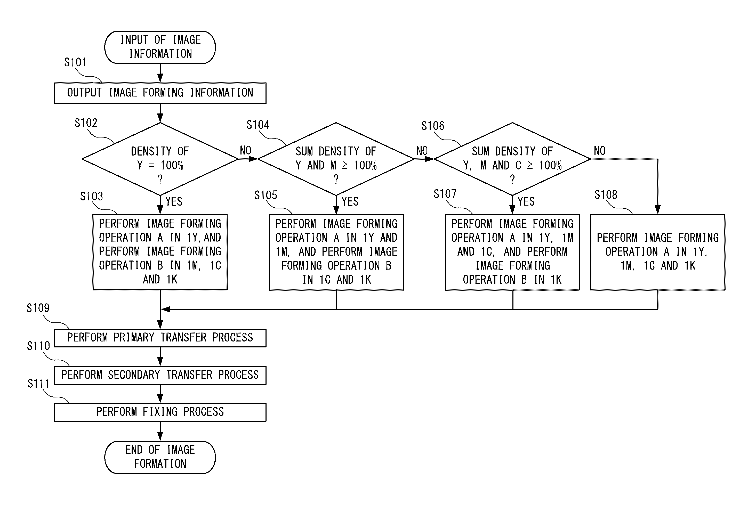
[0048]An image forming apparatus according to Embodiment 2 of the present invention will be described. An overview of the image forming apparatus according to the embodiment is similar to that according to Embodiment 1. The image forming apparatus according to the embodiment has a feature in that which of the image forming operation A and the image forming operation B is selected as the image forming operation in the image forming stations 1 is determined by whether the number of pixels in the image forming information in which the density is equal to or higher than predetermined density is equal to or larger than a predetermined number or not. Points different from those in Embodiment 1 will be mainly described herein, and like reference numerals are used to designate like structural elements which are similar to those in Embodiment 1 and description thereof is omitted. Points which are not described here are similar to those in Embodiment 1.

[0049]

[0050]An image forming sequence in...

embodiment 3

[0058]Embodiment 3 of the present invention will be described. An overview of an image forming apparatus according to the embodiment is similar to that according to Embodiment 1. The image forming apparatus according to the embodiment has a feature in that which of the image forming operation A and the image forming operation B is selected as the image forming operation in the image forming stations 1 is determined in the following way. Specifically, the determination is made by whether the total number of pixels among the pixels in the image forming information in which the density is equal to or higher than density set in advance and pixels in a peripheral region of which also have density that is equal to or higher than the density set in advance is equal to or larger than a predetermined number or not. An image forming sequence of the image forming apparatus of the embodiment according to the present invention will be described with reference to FIG. 2 and FIG. 8.

[0059]FIG. 8 is...


PUM


Abstract

An image forming apparatus including: a plurality of image forming stations; and a control portion configured to control an image forming operation, each of the image forming stations includes: an image bearing member configured to form a toner image on a surface thereof; and a charging device configured to charge the image bearing member, wherein the toner images formed on the image bearing members of the image forming stations are sequentially transferred to a transfer incurring member to be superimposed, wherein the control portion sets a voltage applied to the charging device in forming an image in an image forming station which performs the transfer later based on image density information of the toner image transferred to the transfer incurring member by an image forming station which performs the transfer earlier in a sequence of the image forming operations.

Description

BACKGROUND OF THE INVENTION[0001]1. Field of the Invention[0002]The present invention relates to an electrophotographic image forming apparatus, and more particularly, to a technology of charging and exposure.[0003]2. Description of the Related Art[0004]A typical electrophotographic image forming apparatus includes an image forming station configured to perform toner development with regard to an electrostatic latent image formed by exposing a charged photosensitive drum to form a toner image on the photosensitive drum, and a transfer portion configured to electrostatically transfer the toner image formed on the photosensitive drum to an image-receiving member. An image forming apparatus configured to form a full-color image includes a plurality of image forming stations, and, by transferring in sequence respective single-color toner images formed in the respective image forming stations to an image-receiving member such as an intermediate transfer member or a recording material so ...

Claims


Application Information

Patent Timeline
Patent Type & Authority Applications(United States)
IPC IPC(8): G03G15/02
CPCG03G15/0266G03G15/04
Inventor TETSUNO, SHUICHIHASEGAWA, HIDEAKIKITAMURA, TAKUYA
Owner CANON KK
Why Eureka
Try Eureka