
Explosion mitigating cover

Active Publication Date: 2014-06-19
EAST JORDAN IRON WORKS
View PDF1 Cites 18 Cited by
  • Summary
  • Abstract
  • Description
  • Claims
  • Application Information

AI Technical Summary

Benefits of technology

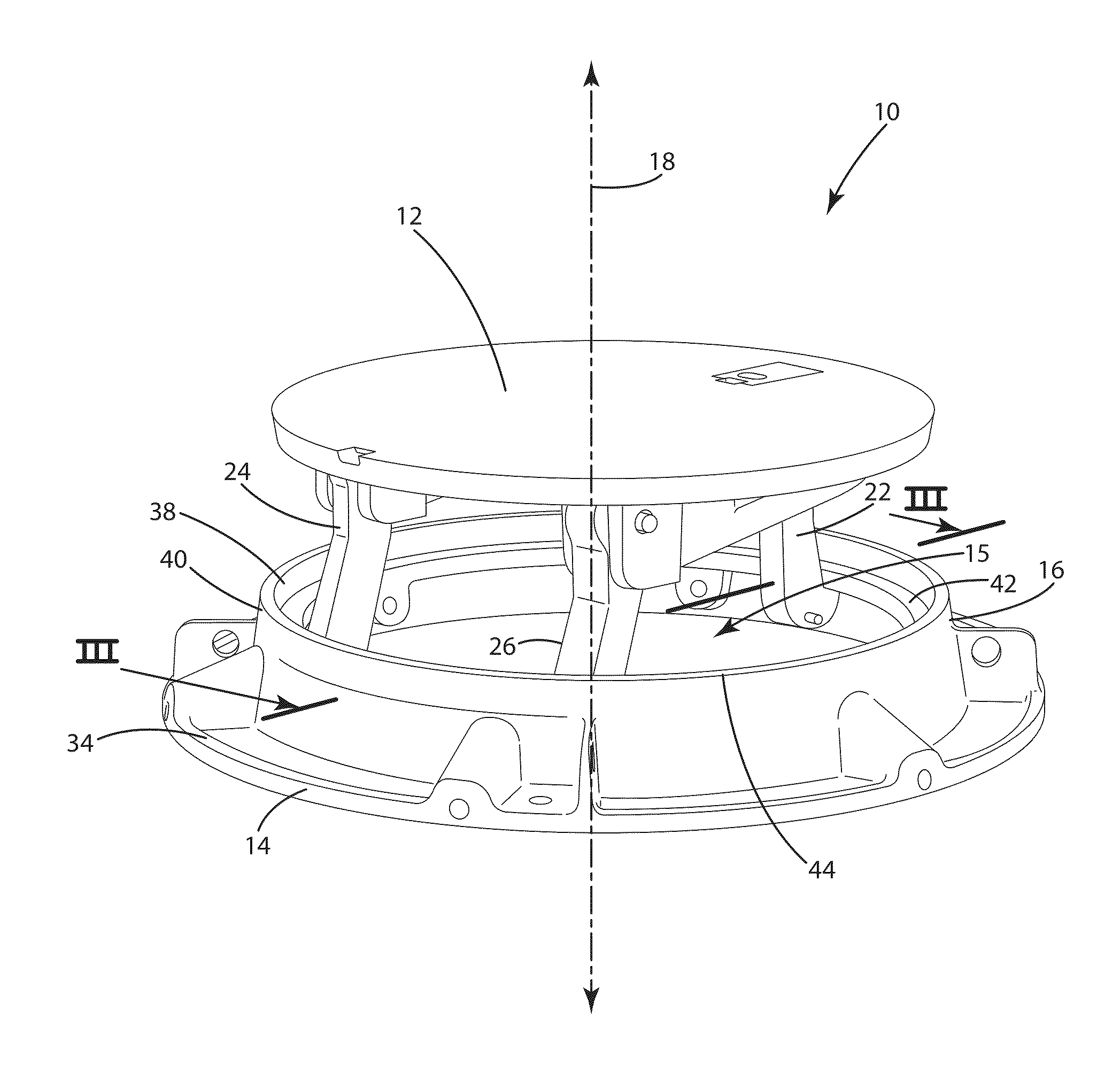
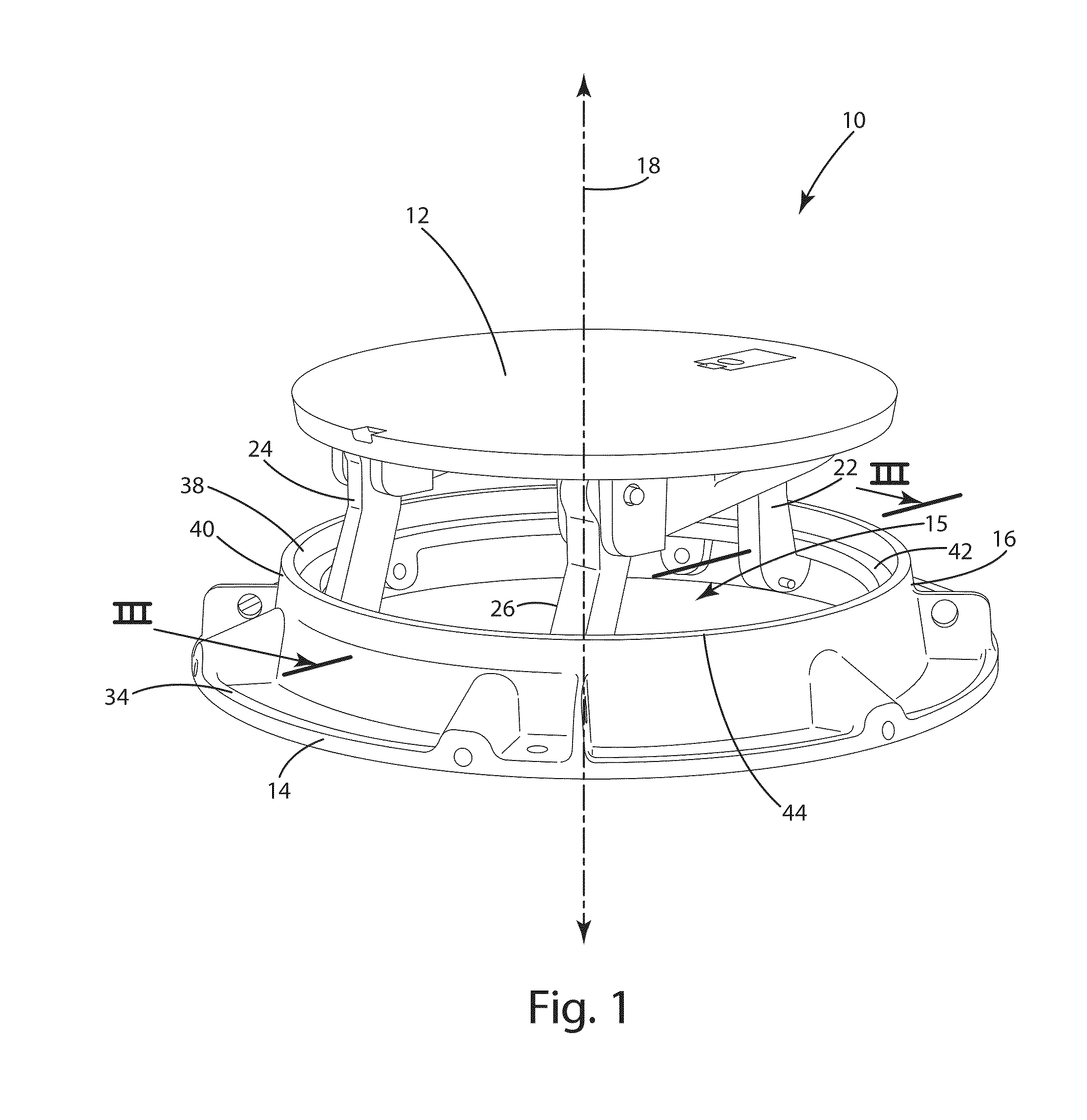
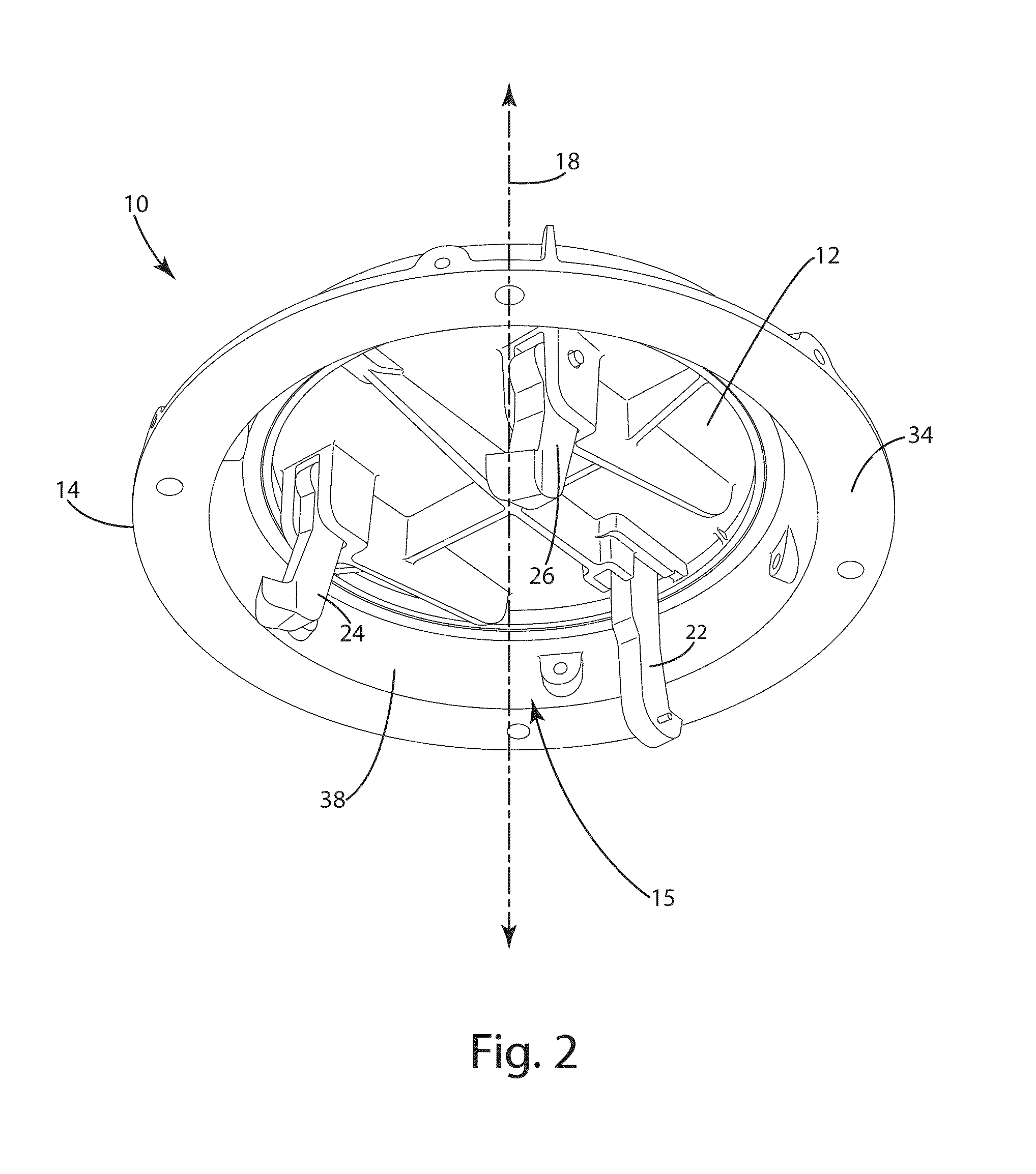
The present invention provides a manhole cover assembly that can act as a relief valve in an explosion event, allowing fluid to vent from the area underneath the cover. The assembly includes a manhole cover and a frame, and it is designed to limit movement of the manhole cover in response to increased pressure on it. The manhole cover can be opened in response to an explosion, allowing air or explosive gas to escape. The assembly can be configured in a restraint mode to prevent complete removal of the manhole cover from the frame, and it can be opened in a removal mode to allow complete removal. The assembly includes pivotable legs that can be configured between the removal mode and the restraint mode, and they interface with the peripheral wall of the frame to limit movement of the manhole cover. The assembly also includes an opening through which a leg can slide in a removal mode, and the leg can be anchored to the manhole cover in a restraint mode to prevent it from being removed. The assembly can limit the direction of flow of any gases, flames, or fluids that escape the manhole during an explosion or other high pressure event.

Problems solved by technology

Despite this weight, electrical or gas explosions in the area underneath the cover may unseat the manhole cover due to the sudden pressure build up from the explosion.
This configuration, however, may not relieve the pressure from an explosion event, thereby potentially causing structural damage to the underground area or to surrounding surface structure, such as the road.
However, this cover assembly is not without drawbacks.
Although the locking lug appears to be a simple component, the extendable latch includes multiple interfitting components, which add expense to the overall product and may become susceptible to failure over time.

Method used


Image

  • Explosion mitigating cover
  • Explosion mitigating cover
  • Explosion mitigating cover

Examples


second embodiment

III. Second Embodiment

[0045]A second embodiment of the explosion mitigating manhole cover is shown in FIGS. 7-15 and generally designated 100. In this second embodiment, the manhole cover assembly 100 generally includes a manhole cover 112 and frame 114 adapted to support the manhole cover 112. As in the first embodiment, the manhole cover 112 is configured to behave as a relief valve in an explosion event, opening so that fluid, such as air, explosive gas, or another gas, may vent through the manhole cover assembly 100. The manhole cover assembly 100 varies from the first embodiment in that upon the pressure under the manhole cover 112 reaching a threshold, the manhole cover 112 lifts angularly—rather than strictly vertically—with respect to the frame 114. As in the first embodiment, the manhole cover 112 is configured to limit the movement of the cover 112 with respect to the frame 114 in response to increased pressure on the manhole cover 112 and to then return the opened portion...


PUM


Abstract

A manhole cover assembly configured to behave as a relief valve in an explosion event, opening so that fluid, such as air or explosive gas, may vent from an underground area. The manhole cover assembly may include a manhole cover and a frame, and may be configured to limit movement of the manhole cover with respect to the frame in response to increased pressure on the manhole cover. In one embodiment, the manhole cover may include legs having angled surfaces adapted to substantially center or guide the manhole cover in the frame while the manhole cover displaces to release pressure. In another embodiment, one or more legs slidable within the manhole cover to enable configuring the manhole cover between a restraint mode and a removal mode.

Description

BACKGROUND OF THE INVENTION[0001]The present invention relates to an explosion mitigating manhole cover, and more particularly to a manhole cover configured to release pressure in a directional manner and limit movement during an explosion event.[0002]Manhole covers are well known. Generally, a manhole cover is a removable plate forming the lid over an opening providing access to an underground area also known as a manhole that may include utilities, pipes, cables and passages. The lid may, among other things, prevent someone from falling in and keep unauthorized persons out. Conventional manhole covers seat on a frame installed over the manhole, sometimes flush with the surface of a road. The frame may provide an interface for the manhole cover to seat over the manhole opening, and often times, is secured to the manhole or surrounding structure so that the manhole cover may be removed for access while the frame remains fixed in place.[0003]Manhole covers often weigh more than 100 p...

Claims


Application Information

Patent Timeline
IPC IPC(8): E02D29/14
CPCE02D29/1436E02D29/14E02D29/1418
Inventor REYNOLDS, DEAN W.ALLEN, JAMES R.JOHNSON, JEREMY I.
Owner EAST JORDAN IRON WORKS
Learn More