Orthodontic Appliance Anchoring Method and Apparatus

a technology of orthodontic appliances and attachment methods, which is applied in the field of orthodontic appliance anchoring and attachment systems, can solve the problems of multiple fitting visits, insufficient space in the dental arch for all teeth to fit properly, and inability to form a perfect fi

Inactive Publication Date: 2014-06-19
PARKER JUSTIN
View PDF3 Cites 11 Cited by
  • Summary
  • Abstract
  • Description
  • Claims
  • Application Information

AI Technical Summary

Benefits of technology

[0044]For example, the invention may be adapted for use with invisalign type appliances. This requires a tooth anchoring structure designed to fit flat onto the lingual or buccal surface of a tooth/teeth via a bracket/band, which follows the profile of the of the anatomy of the tooth tightly as to enable the placement of a plastic invisible removable aligner or retainer over the combined tooth and band/bracket structure. The attachment maintains a thin, low profile tooth attachment bracket/band and continues apically, exiting the invisalign appliance and extends around the anatomy of the soft and hard tissues of the palate buccal/lingual mucosa on either/both the maxilla or mandible. It extends past the border of the overlaid plastic invisible removable aligner so as to be unencumbered by said aligner. At which point, a mechanical clamp accepts the first end of the FFM. Then the second end of the FFM is attached to at least one TAD with a mechanical fastener fitted with an a

Problems solved by technology

This creates a problem when a tooth is not wanted.
In many cases there is insufficient space in the dental arch for all the teeth to fit properly.
These wires are custom bent and formed to the patient and do not necessarily form a perfect fit.
Co

Method used


Image

  • Orthodontic Appliance Anchoring Method and Apparatus
  • Orthodontic Appliance Anchoring Method and Apparatus
  • Orthodontic Appliance Anchoring Method and Apparatus

Examples


Embodiment Construction

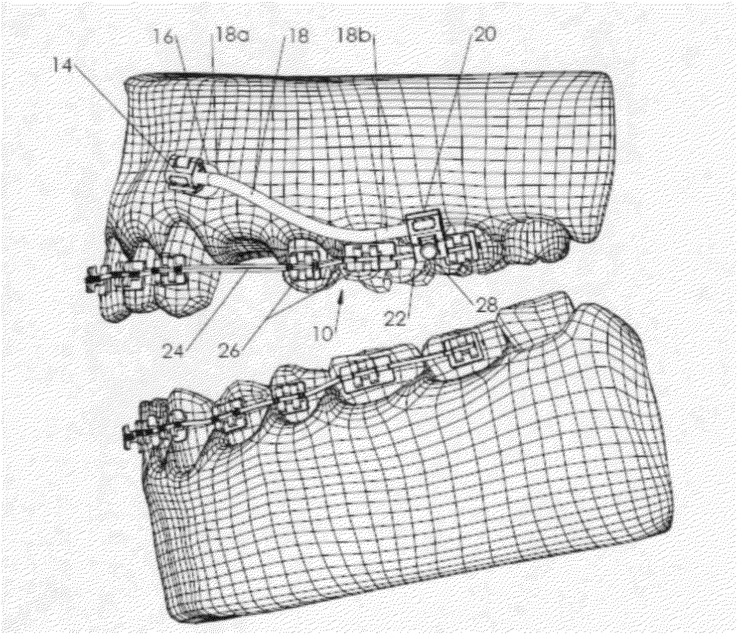
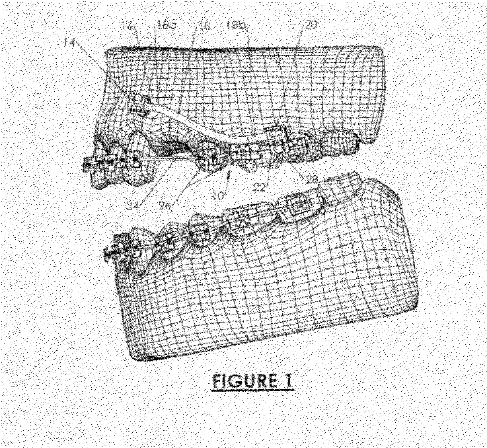
[0085]Examples of the present invention are illustrated in the following figures. FIG. 1 is a perspective view of one embodiment of the invention 10 with a temporary anchoring device (TAD) 12 mounted along the gum line above the teeth of the maxillary arch. At the opposite end a tube and clamp 14 fitted through the traditional arch wire 24 system to provide a stop to the molar of which is now fixed in position and will not move when traditional space closing of the missing first bicuspid is initiated. The temporary anchoring device (TAD) 12 is better shown in FIG. 7 with a mechanical locking device or clamp 14 attached to its head 16 positioned between the teeth to the bone to provide a fixed anchoring point. One end 18a of a flexible curable resin rope 18 is secured by the mechanical locking device or clamp 14 of the TAD 12. The other end 18b is secured to a mechanical locking device 20 affixed to a tube cleat auxiliary 22 fitted to a clamp fastener 20, which accepts an arch wire 2...


PUM


Abstract

Orthodontic anchoring method and custom appliances affixed to teeth, TADs and/or tooth positioning, moving and stabilization appliances and/or orthodontic auxiliaries. Each appliance has mechanical fasteners structured to secure segments of a curable flexible resin rope called a flex fit module (FFM). The FFM is moldable and adaptable to the oral cavity between mechanical fasteners in an uncured first mode where it is cut to length, positioned around the anatomy of the mouth and attached to clamps or fasteners and/or flex fit wafers FFW(s) at each or one end. Each fastener has a clamp or fastener attached to orthodontic auxiliaries, orthodontic appliances or onto a TAD for anchorage purposes. One end of this custom appliance is usually attached via a clamp or fastener manufactured as part of a bracket or band to a tooth. The other end is connected to an appliance, tad, flex fit wafer or auxiliary. Once connected together the system is cured and becomes a solid entity ready to accept orthodontic forces.

Description

RELATED APPLICATIONS[0001]This application is a continuation-in-part patent application of the patent application entitled “Orthodontic Appliance Anchoring Method and Apparatus”, Ser. No. 13 / 487,822 filed Jun. 4, 2012.BACKGROUND OF THE INVENTION[0002]1. Field[0003]This invention pertains to orthodontic anchoring and appliance attachment systems. Specifically, it refers to an orthodontic anchoring and attachment method for teeth connected to orthodontic appliances. These are custom appliances designed on demand by the orthodontist for the anchorage needs and / or appliance development during one visit (after separation for bands in some instances) at the orthodontist. These appliances are affixed to temporary anchorage devices (TADs) and / or teeth and / or orthodontic appliances. Each custom appliance has in common a choice of mechanical fasteners with one or multiple orthodontic auxiliaries and, at least one flexible fit module (FFM), which is a flexible curable resin rope and / or a Flex ...

Claims


Application Information

Patent Timeline
IPC IPC(8): A61C7/10A61C7/28
CPCA61C7/22A61C7/285A61C8/0096A61C7/10A61C7/282
Inventor PARKER, JUSTIN
Owner PARKER JUSTIN
Why Eureka
Try Eureka