
Eureka
For R&D, Eureka makes reading and utilizing patents & technical documents easy.
Eureka AIR
Designed for self-driven R&D workflows. Generate viable solutions, solve complex R&D challenges, empower your innovation with AI.

Eureka Materials
Designed for material experts only. Revolutionize your material R&D, from search, analyze, to developing new materials.

TechResearch
Generate reliable direction feasibility study reports for your R&D in just a few steps.

TechSeek
Discover and master advanced knowledge NOW. Basics, ideas, possibilities, all at once.

TechMind
As an expert in R&D Theories, TechMind can generates customized viable solutions instantly.

TechRisk
Analyze your overall solution with one click, know your potential R&D risks in advance.

TechMonitor
Get weekly tech updates, stay abreast of the latest tech innovations and key insights.
Machine control system employing lathe tool and scraping cutter
- Summary
- Abstract
- Description
- Claims
- Application Information
AI Technical Summary
Benefits of technology
Problems solved by technology
Method used
Image

Examples
Embodiment Construction
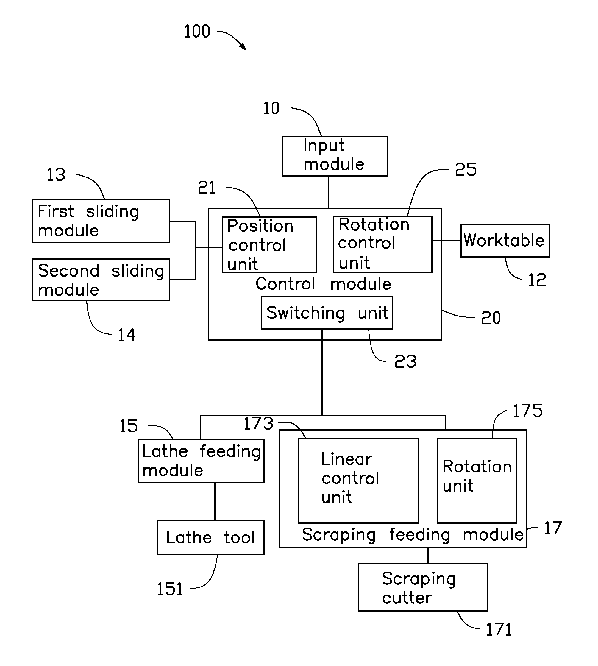
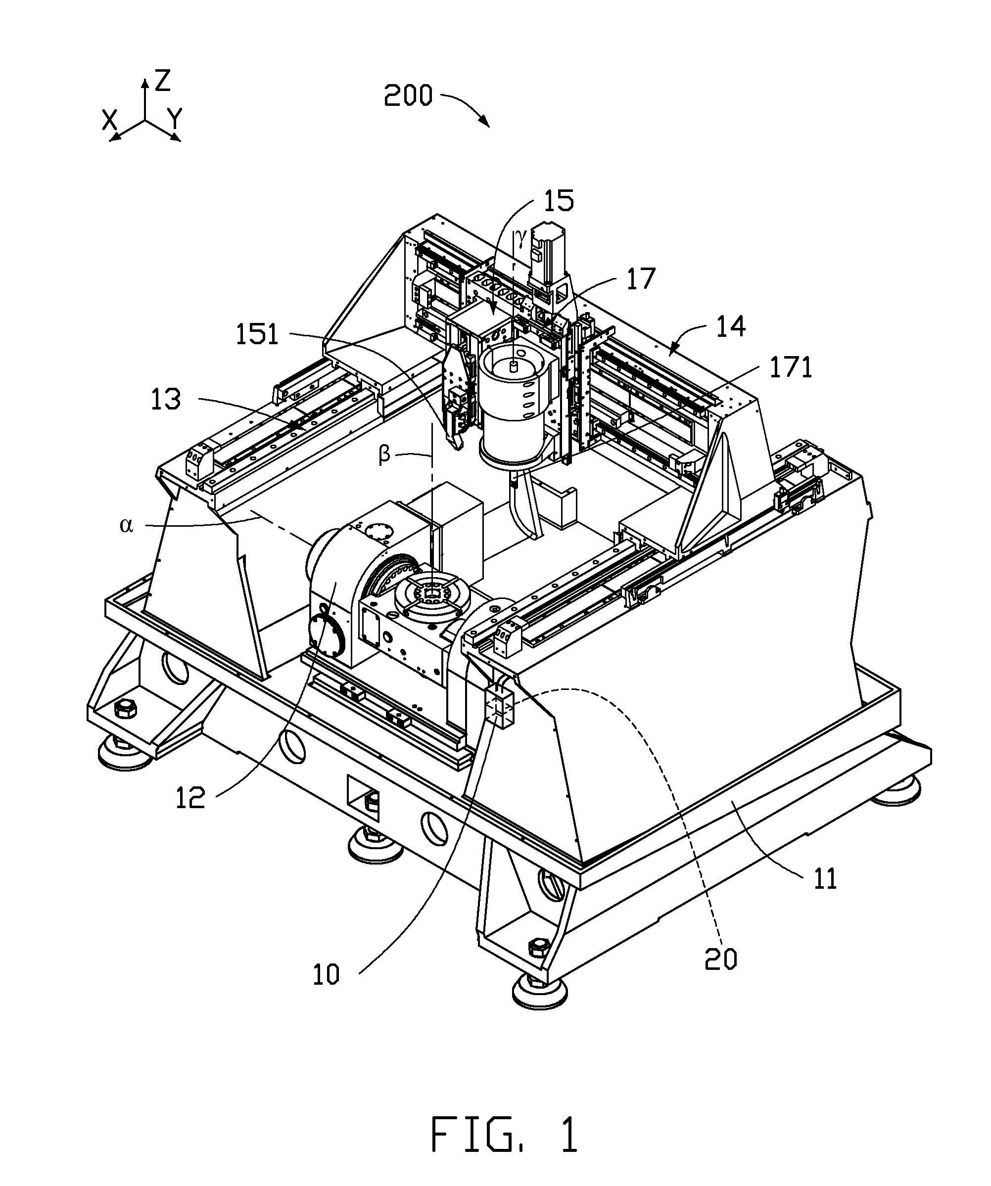
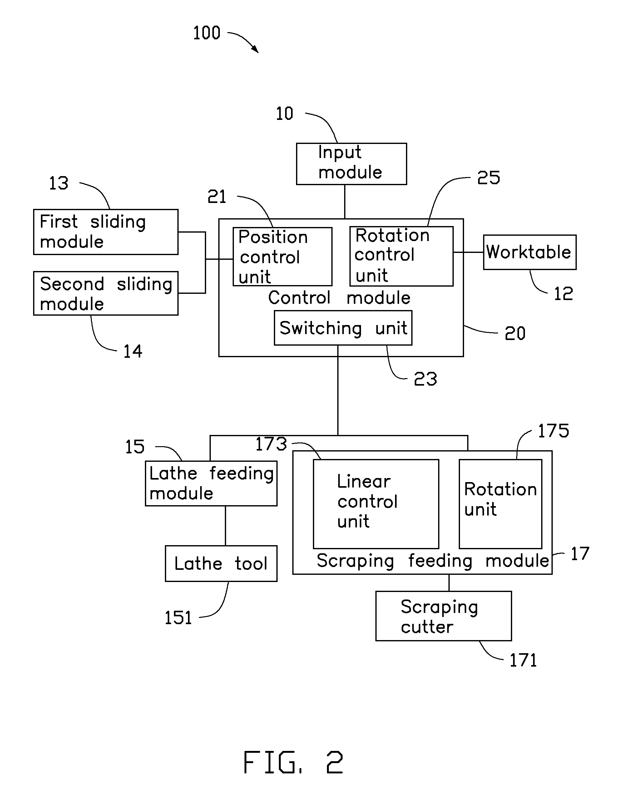
[0014]FIG. 1 shows an embodiment of a machine 200 for machining a metallic member 300 (see FIG. 3). The machine 200 includes an input module 10, a machine support 11, a worktable 12, a first sliding module 13, a second sliding module 14, a lathe feeding module 15, a scraping feeding module 17, and a control module 20 electrically connected to the input module 10. The input module 10 is mounted on a side of the machine support 11. The control module 20 is mounted on a side of the input module 10 and is electrically connected to the input module 10. The worktable 12 is rotatable mounted on the machine support 11. The first sliding module 13 is slidably mounted on the machine support 11 and is positioned above the worktable 12. The second sliding module 14 is sidably mounted on the first sliding module 13. The lathe feeding module 15 and the scraping feeding module 17 are arranged side by side and slidably mounted on the second sliding module 14. The metallic member 300 is held on the ...
PUM
| Property | Measurement | Unit |
|---|---|---|
| Speed | aaaaa | aaaaa |
| Frequency | aaaaa | aaaaa |
Abstract
Description
Claims
Application Information
 - R&D Engineer
- R&D Manager
- IP Professional
- Industry Leading Data Capabilities
- Powerful AI technology
- Patent DNA Extraction
Browse by: Latest US Patents, China's latest patents, Technical Efficacy Thesaurus, Application Domain, Technology Topic, Popular Technical Reports.
© 2024 PatSnap. All rights reserved.Legal|Privacy policy|Modern Slavery Act Transparency Statement|Sitemap|About US| Contact US: help@patsnap.com