Liquid Crystal Display Device and Driving Method Thereof

a display device and liquid crystal technology, applied in the field of display devices, can solve the problems of increasing the load on the display device, insufficient advantages of display devices, increasing other troubles, etc., and achieve the effects of reducing power consumption, increasing manufacturing costs, and reducing the quality of moving images

Inactive Publication Date: 2008-07-31
SEMICON ENERGY LAB CO LTD
View PDF18 Cites 186 Cited by
  • Summary
  • Abstract
  • Description
  • Claims
  • Application Information

AI Technical Summary

Benefits of technology

[0021]Although various methods for solving a problem of motion blur in hold-type display devices have been considered, advantageous effects thereof are not sufficient in some cases. In addition, other troubles are increased by using the methods in some cases. For example, a flicker increases in a method in which display is made closer to that of impulsive-type display devices by displaying a black image. In addition, by displaying the black image, luminance of an image decreases compared with the case of not inserting a black image. In that case, in order to obtain luminance which is equal to that of the case of not inserting a black image, it is necessary to increase luminance instantaneously. Accordingly, loads on display devices are increased to decrease reliability or increase power consumption, which becomes problematic.
[0022]In a method of increasing a frame rate, a driver circuit which can process data at high speed is necessary because data processing becomes complicated, so that manufacturing cost increases, heat is generated in accordance with data processing, and power consumption increases, which become problematic. In addition, in a method in which a new image is generated by compensating image data, it is difficult to obtain high-quality compensated image, and on the contrary, quality of a moving image decreases in some cases by displaying an image by insertion of compensated data.
[0023]Further, when the above-described method for solving a problem of motion blur is applied to a liquid crystal display device, there is a problem in that speed during which transmittance of a liquid crystal is change is slow and it is difficult to sufficiently follow change in signals. Furthermore, there is a problem in that degree of light emission of a pixel is changed depending on viewing angles.
[0024]The present invention has been made in view of the foregoing problems. It is an object of the present invention to provide a hold-type display device without a problem of motion blur and a driving method of thereof. It is another object of the present invention to provide a display device with low power consumption and a driving method of thereof. In addition, it is another object of the present invention to provide a display device with improved quality for still images and moving images and a driving method of thereof. Further, it is another object of the present invention to provide a display device with a wider viewing angle and a driving method of thereof. Furthermore, it is an object of the present invention to provide a display device with improved response speed of a liquid crystal and a driving method of thereof.
[0025]One aspect of the present invention is a driving method of a liquid crystal display device in which an image is displayed by applying signal voltage Vi in accordance with an image signal to a liquid crystal element. One frame period is divided into a first subframe period and a second subframe period. When the length of the first subframe period is denoted by τa, first voltage which is applied to the liquid crystal element in the first subframe period is denoted by Va, and second voltage which is applied to the liquid crystal element in the second subframe period is denoted by Vb, the first voltage V1 is determined in accordance with a difference between the second voltage Vb and the signal voltage Vi, and the length of the first subframe period τa. The second voltage Vb is voltage at which the liquid crystal element performs black display.
[0026]Another aspect of the present invention is a driving method of a liquid crystal display device in which an image is displayed by applying signal voltage Vi in accordance with an image signal to a liquid crystal element. The liquid crystal display device includes a backlight. When the length of a backlight lighting period in one frame period is denoted by τa, first voltage which is applied to the liquid crystal element in one frame period is denoted by Va, and initialization voltage which is applied to the liquid crystal element right before one frame period is denoted by V0, the first voltage V1 is determined in accordance with a difference between the initialization voltage V0 and the signal voltage Vi, and the length of the backlight lighting period τa.

Problems solved by technology

Although various methods for solving a problem of motion blur in hold-type display devices have been considered, advantageous effects thereof are not sufficient in some cases.
In addition, other troubles are increased by using the methods in some cases.
Accordingly, loads on display devices are increased to decrease reliability or increase power consumption, which becomes problematic.
In a method of increasing a frame rate, a driver circuit which can process data at high speed is necessary because data processing becomes complicated, so that manufacturing cost increases, heat is generated in accordance with data processing, and power consumption increases, which become problematic.
In addition, in a method in which a new image is generated by compensating image data, it is difficult to obtain high-quality compensated image, and on the contrary, quality of a moving image decreases in some cases by displaying an image by insertion of compensated data.
Further, when the above-described method for solving a problem of motion blur is applied to a liquid crystal display device, there is a problem in that speed during which transmittance of a liquid crystal is change is slow and it is difficult to sufficiently follow change in signals.
Furthermore, there is a problem in that degree of light emission of a pixel is changed depending on viewing angles.

Method used


Image

  • Liquid Crystal Display Device and Driving Method Thereof
  • Liquid Crystal Display Device and Driving Method Thereof
  • Liquid Crystal Display Device and Driving Method Thereof

Examples


embodiment mode 1

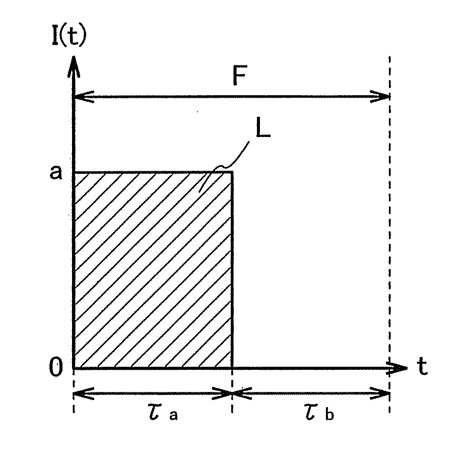
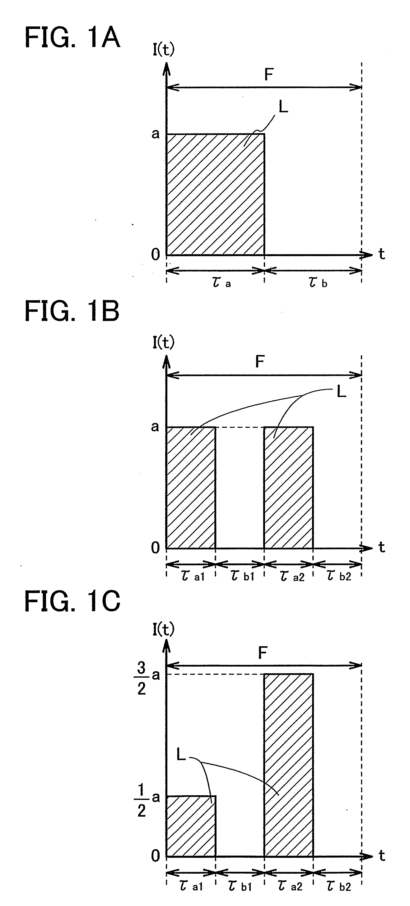
[0198]In this embodiment mode, words relating to a driving method of a display device, such as instantaneous luminance, integrated luminance, a lighting ratio, and average luminance used in this document (the specification, the claim, the drawing, and the like), and control modes thereof are described.

[0199]First, meanings of words and signs used in this document are described. First, words about time and signs thereof, i.e., t, F, τa, τb, and R are described. The sign t expresses time. The sign F expresses one frame period and the length thereof. One frame period F is divided into a plurality of subframe periods, and each of the subframe periods are classified into an image display period or a blanking interval. Here, the image display period is a period during which original luminance of an image is mainly displayed. The blanking interval is a period during which an image displayed in the image display period can be reset by human eyes. Note that the subframe period may be a perio...

embodiment mode 2

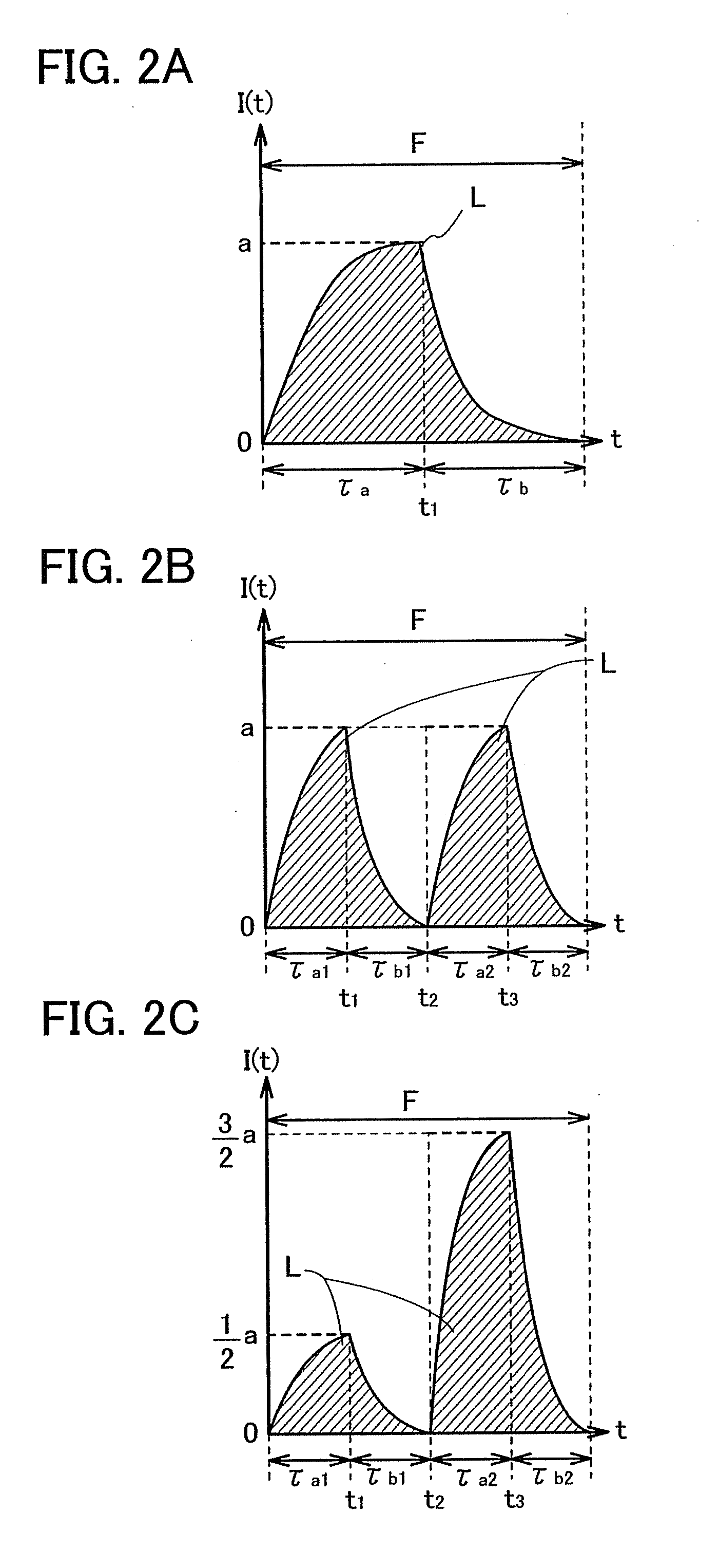
[0290]In this embodiment mode, among methods in each of which the lighting ratio R is changed under a condition that luminance perceived by human eyes is constant and methods in each of which luminance perceived by human eyes is changed, some typical examples are described.

[0291]First, an example of a control method of the lighting ratio R is described. As a control method of the lighting ratio R, (1) a method of directly writing blanking data to each pixel, (2) a method of blinking the whole backlight, and (3) a method of sequentially blinking a backlight which is divided by areas can be mainly given.

[0292]The method (1) can be applied to both the case where a display element included in a display device is a self-luminous element typified by an element included in an EL display, a PDP, or an EFD and the case where a display element included in a display device is a non-light emitting element typified by an element included in a liquid crystal display. The methods (2) and (3) can b...

embodiment mode 3

[0417]In this embodiment mode, specific examples of the control parameter P or Q described in Embodiment Mode 1 are described. In addition, in this embodiment mode, P is used as a sign showing a control parameter.

[0418]Here, in this document, there is not a particular distinction between the case where the sign showing the control parameter is P, the case where the sign showing the control parameter is Q, and the case where the sign showing the control parameter is other than P and Q. The sign showing the control parameter is just determined for convenience. Therefore, among a plurality of specific examples of the control parameter, which are described below, any of the specific examples may be used as the control parameter P, or any of the specific examples may be used as the control parameter Q. In addition, the number of the control parameters is not particularly limited.

[0419]First, the case is described in which the control parameter P is determined by numerically analyzing ima...


PUM


Abstract

To provide a hold-type display device without a problem of motion blur and a driving method thereof. The length of a period for displaying a blanking image in one frame period is controlled in accordance with a control parameter showing the degree of motion blur, and the level of a signal supplied to a display element is changed in accordance with the length of the period for displaying the blanking image. Accordingly, the hold-type display device without a problem of motion blur and the driving method thereof can be provided.

Description

BACKGROUND OF THE INVENTION[0001]1. Field of the Invention[0002]The present invention relates to a display device and an operating method of the display device. In particular, the present invention relates to a method for improving quality of a moving image of a hold-type display device.[0003]2. Description of the Related Art[0004]In recent years, there have been growing interests in thin display devices. Liquid crystal displays, plasma displays, projection displays, and the like have been developed and becoming popular instead of CRT displays. Further, field emission displays, inorganic electroluminescence displays, organic electroluminescence displays, electronic paper, and the like have been developed as next-generation display devices.[0005]In a display portion which is provided in the above-described display device, pixels which are minimum units for forming an image are arranged. Each of the pixels emits light with desired luminance by being supplied with a signal generated by...

Claims


Application Information

Patent Timeline
Patent Type & Authority Applications(United States)
IPC IPC(8): G09G3/36
CPCG09G3/20G09G2310/0237G09G3/2022G09G3/2074G09G3/2081G09G3/22G09G3/3258G09G3/3406G09G3/342G09G3/3648G09G3/3659G09G2300/0465G09G2300/0809G09G2300/0819G09G2300/0842G09G2300/0852G09G2300/0876G09G2300/088G09G2310/0235G09G2310/024G09G2310/0251G09G2310/061G09G2310/08G09G2320/0233G09G2320/0247G09G2320/0252G09G2320/0261G09G2320/028G09G2320/041G09G2320/043G09G2320/0613G09G2320/0646G09G2320/106G09G2330/021G09G2340/16G09G2360/144G09G2360/16H04M1/0214H04M1/0266H04M2250/16H04W52/0251G02F1/13306G09G3/3607G09G3/2018Y02D30/70G02F1/133G09G3/36G09G3/3413G09G3/3677G09G3/3688G09G2320/0257
Inventor YOSHIDA, YASUNORIKIMURA, HAJIME
Owner SEMICON ENERGY LAB CO LTD
Why Eureka
Try Eureka