Method For Displaying The Operating Range Of An Electric Drive Vehicle, And Display

a technology of electric drive vehicle and operating range, which is applied in the direction of battery/fuel cell control arrangement, navigation instruments, instruments, etc., can solve the problems of driver confusion, inconvenient operation, and inability to know exactly the route plan of the driver,

Active Publication Date: 2014-06-19
CONTINENTAL AUTOMOTIVE GMBH
View PDF11 Cites 15 Cited by
  • Summary
  • Abstract
  • Description
  • Claims
  • Application Information

AI Technical Summary

Benefits of technology

[0012]It is the object of the invention to propose a method for displaying the operating range of an electric drive vehicle which offers the driver an interactive system for clearly laid out and dynamic operating range planning.
[0014]In contrast to the methods known from the prior art, according to aspects of the present invention, the user does not need to predetermine a fixed route destination for utilizing the display for planning the operating range but instead receives a display of the current operating range based on his current location determined during the trip and the current state of battery charge determined during the trip, a battery service station being selected in each case as necessary destination point for determining the possible operating range without the driver having to make a special input for this purpose. This applies especially when the driver is moving in a known environment and, after concluding his trips, returns back to the starting position. To this extent, the home position can be predetermined, for example, as destination point. Starting from this position, the driver obtains dynamic control without the necessity for separately setting the destination or for modified input in the case of the desire to change the planned traveling route. As a result, the proposed display is especially user-friendly and can be adapted flexibly to the respective location of the vehicle.
[0021]The representation of the destination point has the advantage that the driver recognizes this destination point on first looking at the map illustration even with an automatically selected destination point and can change it, if necessary, via a user interface.
[0026]For the further improvement of the method proposed according to an aspect of the invention, it is possible to take into consideration in the determination of the maximum operating range additional information about the driving technique (for example average power consumption over one or more past periods), vehicle power consumption management, especially relating to loads switched on and / or information about the topology in the environment around the vehicle, for example from map information of a stored digital map. This information does not necessarily have to be road related but can also be determined from a classification of certain environmental areas in the topology and average power consumptions fitting the classification. In contrast to a road-related evaluation, this has the advantage that the method according to the invention provides accuracy even without the activation of precise guidance to a destination which, according to the invention, is to be avoided. Additionally, it can also be provided as part of the method proposed according to the invention that, if necessary, certain typical power consumptions are determined in a self-learning manner for roads traveled on repeatedly. If necessary, this can be done by a sliding averaging technique or, for example, one weighted with the number of trips on this route.
[0029]The sensor unit of the display device according to an aspect of the invention can preferably have an angle transducer, a wheel sensor, a speed sensor, an acceleration sensor, an inclination sensor, a height sensor and / or a position-finding sensor. Suitable sensors can also be integrated in a so-called IMU (Intertial Measurement Unit) for stabilizing the vehicle.

Problems solved by technology

In principle, it is a problem in the case of electric drive vehicles that the operating range, which is distinctly restricted compared with fuel-operated vehicles, entails distinct losses of flexibility for the driver in his route planning and reaching the desired destinations.
Although the driver can then see whether he can still reach his destination on a direct route, the driver will not know exactly, however, when an intermediate destination is not located precisely on this radial route, whether he can still approach such an intermediate destination.
Taking into consideration that a vehicle also may need to charge or exchange the battery in a battery service station at its final destination, the final destination will frequently not be the actual useful destination of the trip because of the possibility that charging or exchanging the battery might not always be available at the useful destination.
This is cumbersome in that the routes need to be planned elaborately and the next destinations must always be input or confirmed by the user.
This is elaborate and complicated in the case of spontaneous route changes.
However, this does always require a destination to be input, which restricts the flexibility in utilization.
Because there must always be a system-supported route planning, this hinders spontaneous route changes of the driver.

Method used


Image

  • Method For Displaying The Operating Range Of An Electric Drive Vehicle, And Display
  • Method For Displaying The Operating Range Of An Electric Drive Vehicle, And Display
  • Method For Displaying The Operating Range Of An Electric Drive Vehicle, And Display

Examples


Embodiment Construction

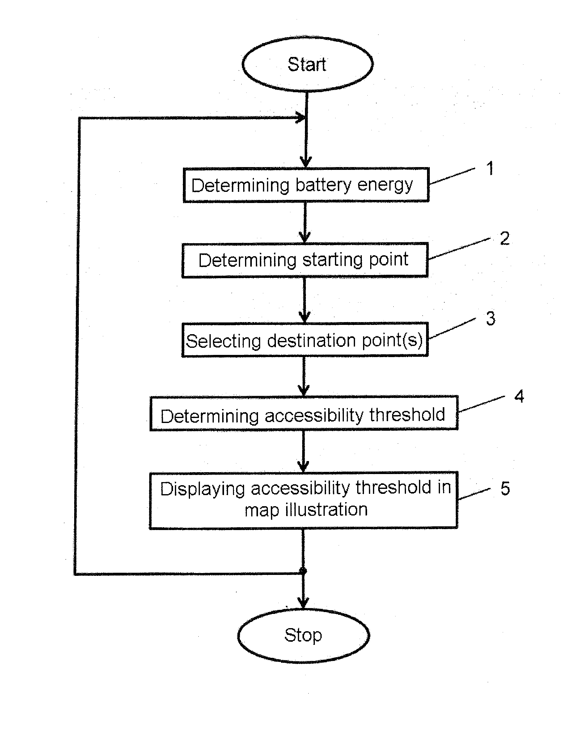
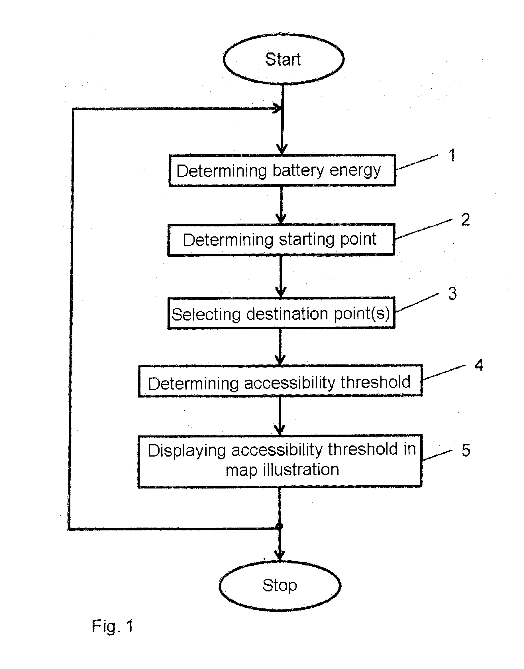
[0039]According to an exemplary embodiment, after the method has been started, a determination of the currently available battery energy takes place in step 1 in the flowchart shown in FIG. 1. This can take place by interrogating an energy management unit provided in the vehicle that continuously monitors the battery charge and displays it, for example, on a display in the cockpit of the vehicle. This status display can also be used for the purposes according to the invention.

[0040]In step 2, the starting point is determined, from which the operating range is to be represented. According to the embodiment, this is, in particular, the respective current starting point of the vehicle, which can be determined preferably by a corresponding position-finding system, for example by satellite positioning. Alternatively, the starting point from which the operating range is to be represented can also be determined via compound navigation and the corresponding sensor information starting from ...


PUM


Abstract

A method and display for displaying the operating range of an electric drive vehicle and a display for carrying out same are provided. The battery energy in a vehicle is detected, and a maximum operating range of the vehicle is determined therefrom. At least one battery service station is selected as destination point for determining the maximum operating range. Based on a starting point, a reachability threshold is determined. If exceeded, the vehicle will be unable to reach the destination point with the current battery energy available, wherein said reachability threshold is displayed as an operating range in a map illustration. During the determination of the reachability threshold, the current location is used as the starting point and the current battery energy of the vehicle is used, both of which are updated at pre-defined intervals while the vehicle is moving.

Description

CROSS-REFERENCE TO RELATED APPLICATIONS[0001]This is a U.S. national stage of application No. PCT / EP2012 / 060974, filed on 11 Jun. 2012, which claims priority to the German Application No. 10 2011 104 153.6, filed 14 Jun. 2011, the content of both incorporated herein by reference.BACKGROUND OF THE INVENTION[0002]1. Field of the Invention[0003]The invention relates to a method for displaying the operating range of an electric drive vehicle and to a corresponding display device which, in particular, is configured for carrying out the method by a computer program product according to the invention. In the method, the battery energy currently available in a vehicle is determined and from this a maximum operating range of the vehicle is derived. The battery is typically constructed in the form of an accumulator and delivers the electrical energy for the electric drive. For determining the maximum operating range, at least one battery service station is selected as a destination point in t...

Claims


Application Information

Patent Timeline
Patent Type & Authority Applications(United States)
IPC IPC(8): B60L11/18
CPCB60L11/1861B60L2240/12B60L2240/18B60L2240/20B60L2240/461B60L2240/622B60L2240/642B60L2250/16B60L2260/52G01C21/3469Y02T90/16B60W2050/146Y02T10/84Y02T10/72Y02T10/70B60L58/12
Inventor KUHN, THOMASMEIER, HERBERTNGUYEN THIEN, NHUSTEGE, ALEXANDER
Owner CONTINENTAL AUTOMOTIVE GMBH
Why Eureka
Try Eureka